Cirkit Designer Logo
Cirkit Designer
Your all-in-one circuit design IDE
Home / 
Component Documentation

How to Use MKE-S16 I2C Line Follower Sensor: Examples, Pinouts, and Specs

Image of MKE-S16 I2C Line Follower Sensor
Cirkit Designer LogoDesign with MKE-S16 I2C Line Follower Sensor in Cirkit Designer

Introduction

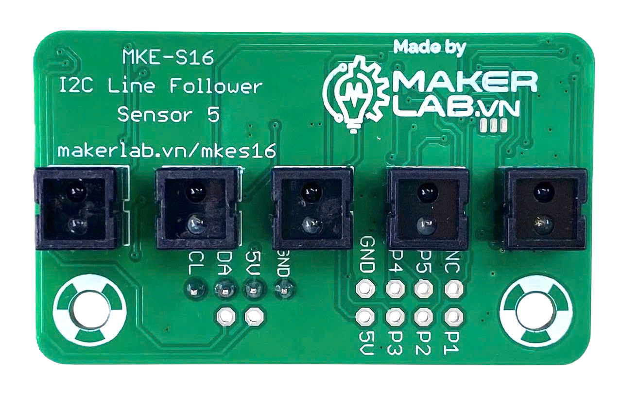
The MKE-S16 I2C Line Follower Sensor, manufactured by Makerlabvn, is a versatile and efficient sensor designed for robotics applications. It is primarily used to detect and follow lines on a surface, making it an essential component for line-following robots. The sensor employs an array of infrared (IR) sensors to detect the contrast between a line (typically black) and the surrounding surface (typically white or light-colored).

The MKE-S16 communicates via the I2C protocol, allowing seamless integration with microcontrollers such as Arduino, Raspberry Pi, and other development boards. Its compact design and reliable performance make it ideal for educational projects, hobbyist robotics, and industrial automation systems.

Explore Projects Built with MKE-S16 I2C Line Follower Sensor

Use Cirkit Designer to design, explore, and prototype these projects online. Some projects support real-time simulation. Click "Open Project" to start designing instantly!
MakerEdu Creator with Bluetooth, IR Sensors, LCD Display, and Push Button Interaction
Image of MKL Distance Measurement: A project utilizing MKE-S16 I2C Line Follower Sensor in a practical application
This circuit features a MakerEdu Creator microcontroller board interfaced with two MKE-S11 IR Infrared Obstacle Avoidance Sensors, a MKE-M02 Push Button Tact Switch, a MKE-M15 Bluetooth module, and a MKE-M08 LCD2004 I2C display module. The push button is connected to a digital input for user interaction, while the IR sensors are likely used for detecting obstacles. The Bluetooth module enables wireless communication, and the LCD display provides a user interface for displaying information or statuses.
Cirkit Designer LogoOpen Project in Cirkit Designer
Raspberry Pi Zero W Based Line Tracking and Obstacle Detection System
Image of CSC615-Assignment#4-LineSensor: A project utilizing MKE-S16 I2C Line Follower Sensor in a practical application
This circuit integrates a Raspberry Pi Zero W with two sensors: a KY-033 Line Tracking Sensor and an FC-51 IR Sensor. The Raspberry Pi is configured to receive digital input signals from the KY-033 sensor on GPIO 04 and from the FC-51 sensor on GPIO 24. The circuit is designed for object detection and line tracking applications, with the Raspberry Pi processing the sensor inputs for decision-making tasks.
Cirkit Designer LogoOpen Project in Cirkit Designer
Raspberry Pi Zero W-Based Health Monitoring System with LoRa and GPS
Image of PET COLLAR: A project utilizing MKE-S16 I2C Line Follower Sensor in a practical application
This circuit is a multi-sensor data acquisition system powered by a Raspberry Pi Zero W. It integrates various sensors including a temperature sensor (LM35), an MPU-6050 accelerometer and gyroscope, a MAX30102 pulse oximeter, a GPS module, and a LoRa module for wireless communication. The system collects environmental and physiological data, which can be transmitted wirelessly via the LoRa module.
Cirkit Designer LogoOpen Project in Cirkit Designer
Arduino Mega 2560-Based Smart Sensor Hub with Battery Power
Image of PROTOTYPE TEST: A project utilizing MKE-S16 I2C Line Follower Sensor in a practical application
This circuit is a sensor-based data acquisition system using an Arduino Mega 2560. It integrates various sensors including an MPU-6050 accelerometer, HC-SR04 ultrasonic sensor, DHT11 temperature and humidity sensor, GPS NEO 6M, MQ135 gas sensor, and multiple IR sensors, all powered by a 2.1mm barrel jack and 18650 Li-ion batteries. The system is designed to collect and transmit environmental data via Bluetooth using an HC-06 module.
Cirkit Designer LogoOpen Project in Cirkit Designer

Explore Projects Built with MKE-S16 I2C Line Follower Sensor

Use Cirkit Designer to design, explore, and prototype these projects online. Some projects support real-time simulation. Click "Open Project" to start designing instantly!
Image of MKL Distance Measurement: A project utilizing MKE-S16 I2C Line Follower Sensor in a practical application
MakerEdu Creator with Bluetooth, IR Sensors, LCD Display, and Push Button Interaction
This circuit features a MakerEdu Creator microcontroller board interfaced with two MKE-S11 IR Infrared Obstacle Avoidance Sensors, a MKE-M02 Push Button Tact Switch, a MKE-M15 Bluetooth module, and a MKE-M08 LCD2004 I2C display module. The push button is connected to a digital input for user interaction, while the IR sensors are likely used for detecting obstacles. The Bluetooth module enables wireless communication, and the LCD display provides a user interface for displaying information or statuses.
Cirkit Designer LogoOpen Project in Cirkit Designer
Image of CSC615-Assignment#4-LineSensor: A project utilizing MKE-S16 I2C Line Follower Sensor in a practical application
Raspberry Pi Zero W Based Line Tracking and Obstacle Detection System
This circuit integrates a Raspberry Pi Zero W with two sensors: a KY-033 Line Tracking Sensor and an FC-51 IR Sensor. The Raspberry Pi is configured to receive digital input signals from the KY-033 sensor on GPIO 04 and from the FC-51 sensor on GPIO 24. The circuit is designed for object detection and line tracking applications, with the Raspberry Pi processing the sensor inputs for decision-making tasks.
Cirkit Designer LogoOpen Project in Cirkit Designer
Image of PET COLLAR: A project utilizing MKE-S16 I2C Line Follower Sensor in a practical application
Raspberry Pi Zero W-Based Health Monitoring System with LoRa and GPS
This circuit is a multi-sensor data acquisition system powered by a Raspberry Pi Zero W. It integrates various sensors including a temperature sensor (LM35), an MPU-6050 accelerometer and gyroscope, a MAX30102 pulse oximeter, a GPS module, and a LoRa module for wireless communication. The system collects environmental and physiological data, which can be transmitted wirelessly via the LoRa module.
Cirkit Designer LogoOpen Project in Cirkit Designer
Image of PROTOTYPE TEST: A project utilizing MKE-S16 I2C Line Follower Sensor in a practical application
Arduino Mega 2560-Based Smart Sensor Hub with Battery Power
This circuit is a sensor-based data acquisition system using an Arduino Mega 2560. It integrates various sensors including an MPU-6050 accelerometer, HC-SR04 ultrasonic sensor, DHT11 temperature and humidity sensor, GPS NEO 6M, MQ135 gas sensor, and multiple IR sensors, all powered by a 2.1mm barrel jack and 18650 Li-ion batteries. The system is designed to collect and transmit environmental data via Bluetooth using an HC-06 module.
Cirkit Designer LogoOpen Project in Cirkit Designer

Common Applications

  • Line-following robots for educational and competitive robotics
  • Automated guided vehicles (AGVs) in warehouses or factories
  • Path-tracking systems in smart toys and robotic kits
  • Obstacle avoidance and navigation systems (when combined with other sensors)

Technical Specifications

Key Technical Details

Parameter Value
Operating Voltage 3.3V to 5V
Communication Protocol I2C
I2C Address (Default) 0x40
Number of IR Sensors 16
Detection Range 2mm to 10mm above the surface
Current Consumption ~30mA
Dimensions 100mm x 15mm x 5mm
Weight 10g
Operating Temperature -10°C to 50°C

Pin Configuration and Descriptions

Pin Name Type Description
VCC Power Power supply input (3.3V to 5V)
GND Ground Ground connection
SDA Data Line I2C data line for communication
SCL Clock Line I2C clock line for communication

Usage Instructions

How to Use the MKE-S16 in a Circuit

  1. Power the Sensor: Connect the VCC pin to a 3.3V or 5V power source and the GND pin to the ground of your microcontroller.
  2. I2C Connection: Connect the SDA and SCL pins of the sensor to the corresponding I2C pins on your microcontroller. For an Arduino UNO, connect:
    • SDA to A4
    • SCL to A5
  3. Mounting: Position the sensor 2mm to 10mm above the surface to ensure accurate line detection.
  4. Programming: Use the I2C protocol to read data from the sensor. The sensor outputs a 16-bit value representing the line position.

Important Considerations and Best Practices

  • Ensure the surface has a high contrast between the line and the background for optimal performance.
  • Avoid direct sunlight or strong ambient IR light, as it may interfere with the sensor's readings.
  • Use pull-up resistors (typically 4.7kΩ) on the SDA and SCL lines if your microcontroller does not have internal pull-ups enabled.
  • Regularly clean the sensor to remove dust or debris that may affect detection accuracy.

Example Code for Arduino UNO

Below is an example Arduino sketch to interface with the MKE-S16 sensor and read line position data:

#include <Wire.h> // Include the Wire library for I2C communication

#define SENSOR_ADDRESS 0x40 // Default I2C address of the MKE-S16 sensor

void setup() {
  Wire.begin(); // Initialize I2C communication
  Serial.begin(9600); // Start serial communication for debugging
  Serial.println("MKE-S16 Line Follower Sensor Initialized");
}

void loop() {
  Wire.beginTransmission(SENSOR_ADDRESS); // Start communication with the sensor
  Wire.write(0x00); // Request data from the sensor
  Wire.endTransmission();

  Wire.requestFrom(SENSOR_ADDRESS, 2); // Request 2 bytes of data
  if (Wire.available() == 2) { // Check if 2 bytes are available
    uint16_t linePosition = Wire.read() << 8 | Wire.read(); 
    // Combine the two bytes into a 16-bit value

    Serial.print("Line Position: ");
    Serial.println(linePosition); // Print the line position
  } else {
    Serial.println("Error: No data received from sensor");
  }

  delay(100); // Wait 100ms before the next reading
}

Troubleshooting and FAQs

Common Issues and Solutions

Issue Possible Cause Solution
No data received from the sensor Incorrect I2C address or wiring issue Verify the I2C address and check all connections
Inconsistent or inaccurate line detection Sensor height is not within the recommended range Adjust the sensor height to 2mm-10mm above the surface
Sensor not responding Missing pull-up resistors on I2C lines Add 4.7kΩ pull-up resistors to SDA and SCL
Interference from ambient light Strong IR light in the environment Use the sensor in a controlled lighting environment

FAQs

  1. Can the I2C address be changed?

    • No, the MKE-S16 has a fixed I2C address of 0x40.
  2. What is the maximum detection range?

    • The sensor can detect lines at a height of up to 10mm above the surface.
  3. Can the sensor detect curved lines?

    • Yes, the sensor can detect curved lines as long as the line remains within the sensor's detection range.
  4. Is the sensor compatible with 3.3V microcontrollers?

    • Yes, the MKE-S16 operates at both 3.3V and 5V, making it compatible with a wide range of microcontrollers.

This concludes the documentation for the MKE-S16 I2C Line Follower Sensor. For further assistance, refer to the manufacturer's datasheet or contact Makerlabvn support.