How to Use Qwiic_OLED_Breakout: Examples, Pinouts, and Specs
Introduction
The Qwiic OLED Breakout is a versatile and compact display module that utilizes organic light-emitting diode (OLED) technology to provide a high-contrast, high-resolution visual output. This breakout board is designed for easy integration into projects with its I2C communication protocol support, making it ideal for applications requiring a small display with low power consumption. Common applications include wearable devices, handheld instruments, and user interfaces for small-scale projects.
Explore Projects Built with Qwiic_OLED_Breakout


Explore Projects Built with Qwiic_OLED_Breakout
Technical Specifications
Key Technical Details
- Display Type: OLED, Monochrome
- Resolution: 128x64 pixels
- Communication: I2C (Qwiic Connect System)
- Operating Voltage: 3.3V
- Maximum Current: 20mA (typical usage)
- Operating Temperature: -40°C to 70°C
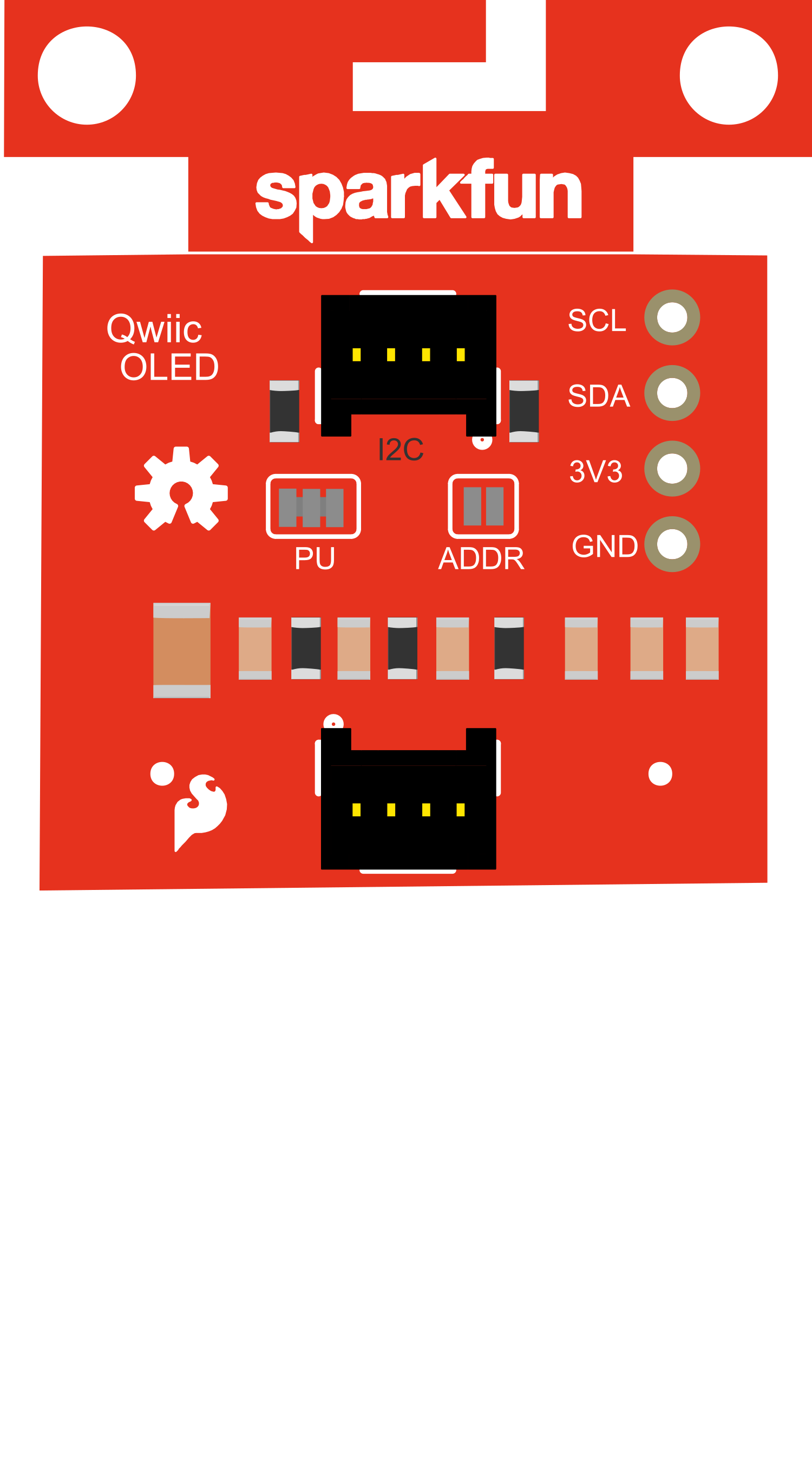
Pin Configuration and Descriptions
| Pin Number | Pin Name | Description |
|---|---|---|
| 1 | GND | Ground, 0V reference for the power supply |
| 2 | 3.3V | Power supply input, 3.3V |
| 3 | SDA | I2C Data Line |
| 4 | SCL | I2C Clock Line |
| 5 | INT | Interrupt pin (not used in all setups) |
Usage Instructions
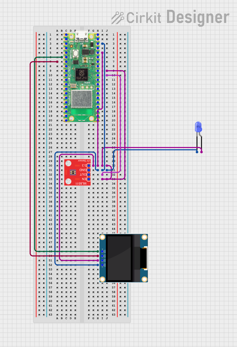
Integrating the Qwiic OLED Breakout into a Circuit
- Power Connections: Connect the GND pin to the ground of your power supply, and the 3.3V pin to a 3.3V source.
- I2C Connections: Connect the SDA and SCL pins to the I2C data and clock lines, respectively. If using with an Arduino UNO, SDA connects to A4 and SCL to A5.
- Mounting: Secure the breakout board to your project using the mounting holes provided, ensuring no shorts occur with the underlying surface.
Important Considerations and Best Practices
- Logic Levels: Ensure that the logic levels of your microcontroller match the 3.3V levels required by the Qwiic OLED Breakout.
- Power Supply: Do not exceed the recommended operating voltage of 3.3V.
- I2C Address: The default I2C address for the Qwiic OLED Breakout is typically 0x3D. Check the datasheet for your specific module as some may have configurable addresses.
- Library: Use a compatible library for interfacing with the OLED display. For Arduino, libraries such as
Adafruit_SSD1306can be used.
Example Code for Arduino UNO
#include <Wire.h>
#include <Adafruit_GFX.h>
#include <Adafruit_SSD1306.h>

#define SCREEN_WIDTH 128 // OLED display width, in pixels
#define SCREEN_HEIGHT 64 // OLED display height, in pixels
#define OLED_RESET     -1 // Reset pin # (or -1 if sharing Arduino reset pin)
#define SCREEN_ADDRESS 0x3D // See datasheet for Address; 0x3D for 128x64

Adafruit_SSD1306 display(SCREEN_WIDTH, SCREEN_HEIGHT, &Wire, OLED_RESET);

void setup() {
  // Initialize with the I2C addr 0x3D (for the 128x64)
  if(!display.begin(SSD1306_SWITCHCAPVCC, SCREEN_ADDRESS)) {
    Serial.println(F("SSD1306 allocation failed"));
    for(;;); // Don't proceed, loop forever
  }
  display.display();
  delay(2000); // Pause for 2 seconds

  // Clear the buffer
  display.clearDisplay();

  // Draw a single pixel in white
  display.drawPixel(10, 10, SSD1306_WHITE);

  // Show the display buffer on the screen
  display.display();
}

void loop() {
  // Nothing to do here
}
Troubleshooting and FAQs
Common Issues
- Display Not Powering On: Check the power connections and ensure the 3.3V and GND pins are correctly connected.
- No Display Output: Verify that the I2C connections are secure and that the correct I2C address is being used in your code.
- Garbled Display: Reset the display power, check for correct library installation, and ensure that the display buffer is being properly cleared before writing new content.
Solutions and Tips for Troubleshooting
- Power Issues: Use a multimeter to check the voltage at the 3.3V and GND pins.
- I2C Communication: Use an I2C scanner sketch to confirm the device's address and connectivity.
- Library Issues: Reinstall the library and ensure it is compatible with your OLED model.
FAQs
Q: Can I use the Qwiic OLED Breakout with a 5V system? A: While the display operates at 3.3V, some 5V systems can safely interface with it through level shifters or if the microcontroller's I2C pins are 3.3V tolerant.
Q: How do I change the I2C address? A: The I2C address can sometimes be changed via solder jumpers or switches on the breakout board. Refer to the specific board's datasheet for instructions.
Q: Can I use multiple Qwiic OLED Breakouts on the same I2C bus? A: Yes, if the breakout allows for address reconfiguration, you can have multiple displays with different addresses on the same I2C bus.