How to Use 6 Core 22awg Wire: Examples, Pinouts, and Specs

 Design with 6 Core 22awg Wire in Cirkit Designer
Introduction
The 6 Core 22awg Wire is a versatile and commonly used electrical wire that features six individual conductors, each of 22 American Wire Gauge (AWG) size. This type of wire is designed for low-voltage applications and is often used in electronics, robotics, and control systems where multiple signals or power connections need to be routed through the same cable.
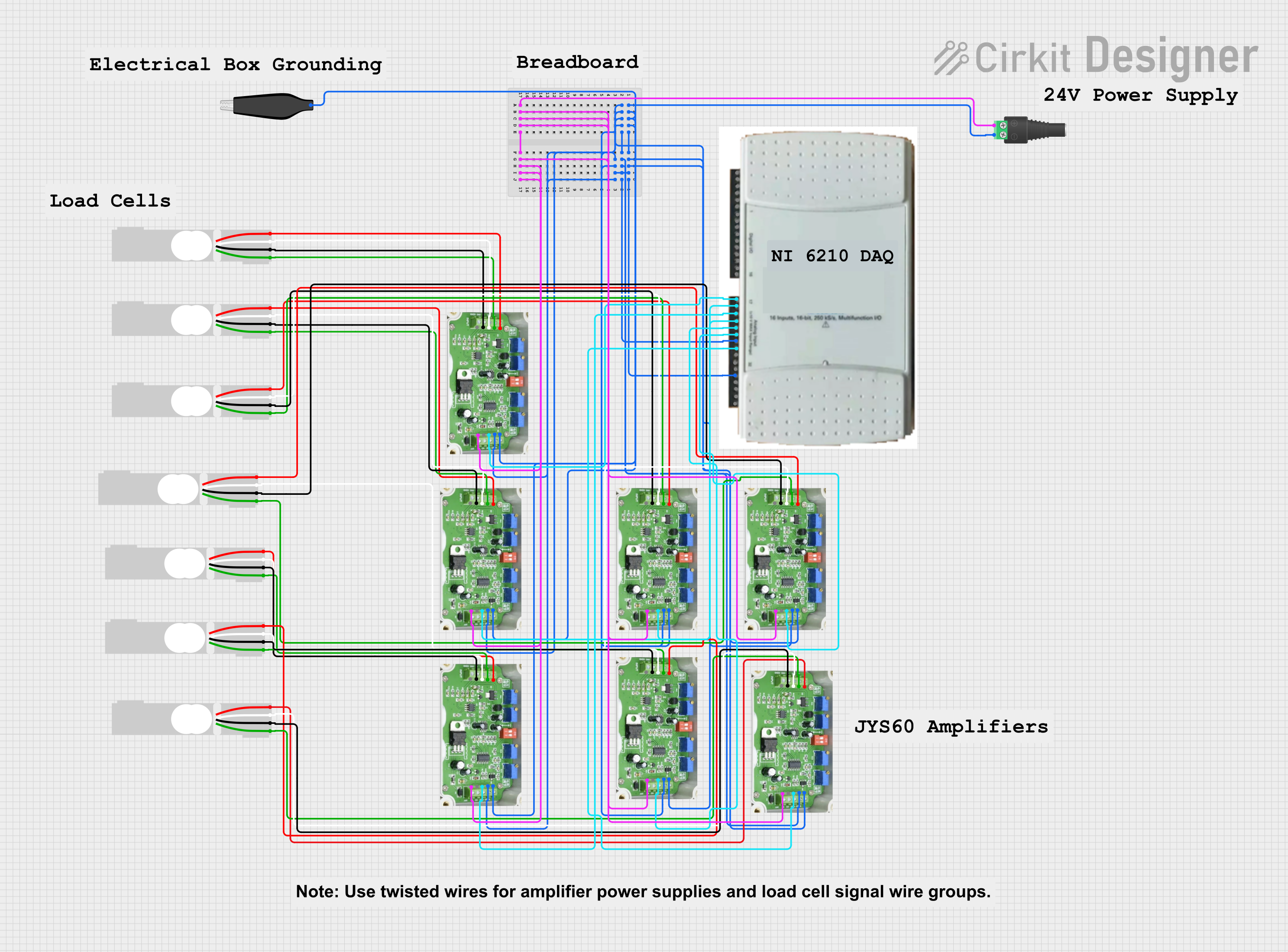
Explore Projects Built with 6 Core 22awg Wire

 Open Project in Cirkit Designer
 Open Project in Cirkit Designer
 Open Project in Cirkit Designer
 Open Project in Cirkit Designer
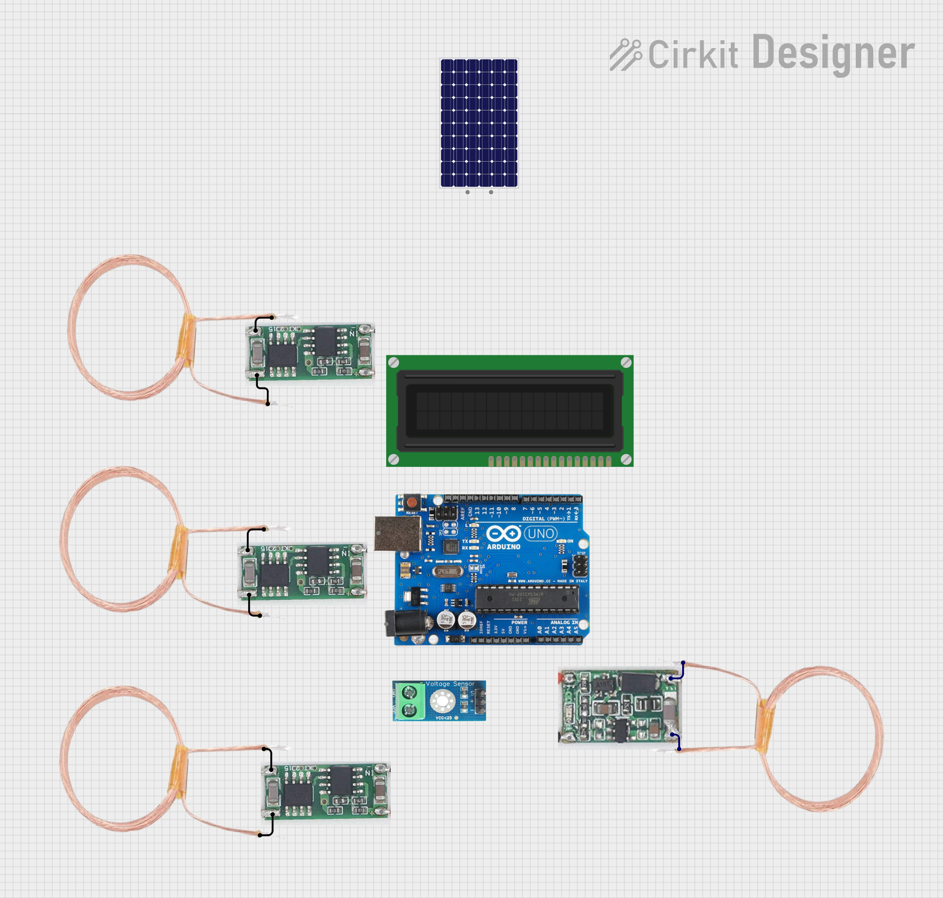
Explore Projects Built with 6 Core 22awg Wire

 Open Project in Cirkit Designer
 Open Project in Cirkit Designer
 Open Project in Cirkit Designer
 Open Project in Cirkit Designer
Common Applications and Use Cases
- Interconnecting electronic devices
- Signal transmission in control systems
- Power distribution in low-voltage circuits
- Data communication in networking hardware
- Robotics and automation wiring
Technical Specifications
Key Technical Details
- Conductor Size: 22 AWG
- Number of Cores: 6
- Voltage Rating: Typically up to 300V
- Current Rating: Dependent on insulation material and environmental factors
- Insulation Material: PVC, Teflon, or others depending on the specific wire type
- Temperature Range: Varies with insulation, commonly -20°C to 80°C
Pin Configuration and Descriptions
| Core Number | Color (Typical) | Recommended Use |
|---|---|---|
| 1 | Red | Power (Vcc) |
| 2 | Black | Ground (GND) |
| 3 | White | Signal 1 |
| 4 | Green | Signal 2 |
| 5 | Blue | Signal 3 |
| 6 | Yellow | Signal 4 |
Note: The color coding can vary depending on the manufacturer. Always check the wire's datasheet for exact color coding.
Usage Instructions
How to Use the Component in a Circuit
- Identify the Wires: Use the wire's color code to identify each core's intended purpose.
- Stripping the Insulation: Carefully strip the outer insulation and individual conductor insulation as needed without damaging the wire strands.
- Soldering: Tin the exposed wire strands with solder before connecting them to other components or terminals to ensure a good electrical connection.
- Connection: Connect each core to the appropriate terminal or component according to your circuit design.
- Insulation: Use heat-shrink tubing or electrical tape to insulate any exposed conductors.
Important Considerations and Best Practices
- Current Limitations: Do not exceed the current rating of the wire to prevent overheating and potential fire hazards.
- Signal Integrity: For signal wires, keep them as short as possible to minimize signal degradation.
- Avoid Sharp Bends: To prevent damage to the wire, avoid bending it at sharp angles.
- Cable Management: Bundle and route the wires neatly to prevent tangling and reduce interference.
- Environmental Factors: Consider the environmental conditions where the wire will be used and ensure the insulation material is suitable for the temperature and exposure.
Troubleshooting and FAQs
Common Issues Users Might Face
- Intermittent Connections: Caused by loose connections or damaged wires. Check solder joints and ensure the wire is not broken.
- Signal Noise: Electromagnetic interference can affect signal wires. Use twisted pairs within the cable if possible and consider shielding.
- Insulation Damage: Physical damage to the insulation can cause shorts. Inspect the wire for cuts or nicks and replace if necessary.
Solutions and Tips for Troubleshooting
- Continuity Testing: Use a multimeter to check for continuity in each core to ensure there are no breaks in the wire.
- Insulation Resistance Testing: Test for potential shorts between cores by measuring the insulation resistance.
- Visual Inspection: Regularly inspect the wire for any physical damage or signs of wear.
FAQs
Q: Can I use 6 Core 22awg Wire for power applications? A: Yes, but ensure the current does not exceed the wire's rating and that the voltage is within the specified limits.
Q: How do I determine the maximum current for each core? A: The maximum current depends on the insulation material and environmental factors. Refer to the manufacturer's datasheet for specific ratings.
Q: Can I use this wire for outdoor applications? A: It depends on the insulation material. Some wires are rated for outdoor use, while others are not. Check the wire's specifications for environmental ratings.
Note: This documentation is for informational purposes only. Always consult a professional engineer for critical applications.
Since the 6 Core 22awg Wire is not an active electronic component and does not interface directly with microcontrollers like an Arduino UNO, code examples are not applicable for this documentation. However, if you are using this wire to connect components to an Arduino, ensure that the connections are secure and that the wire's specifications match the requirements of your project.