How to Use Serial Enabled LCD Backpack: Examples, Pinouts, and Specs
Introduction
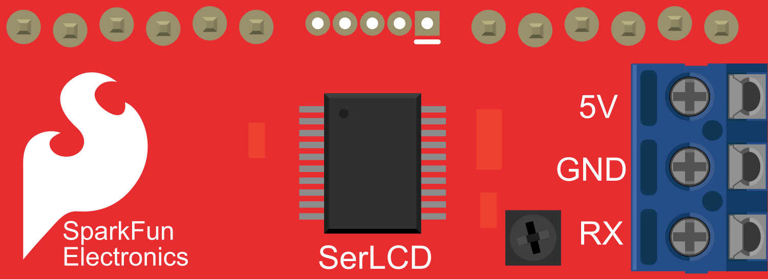
The Serial Enabled LCD Backpack is an electronic component designed to facilitate the integration of an LCD display with microcontrollers or computers through a serial interface. This backpack module simplifies the process of connecting and controlling an LCD by handling the low-level communication, allowing users to focus on displaying text and other information. Common applications include user interfaces, data monitoring displays, and any project requiring textual output to an LCD.
Explore Projects Built with Serial Enabled LCD Backpack


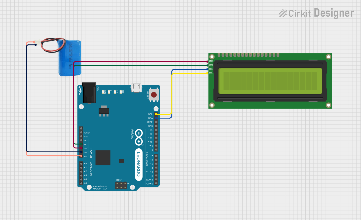
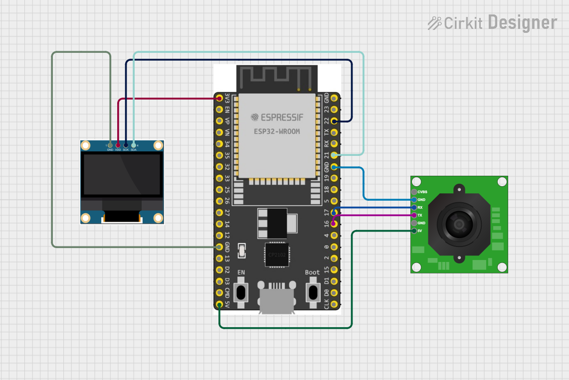
Explore Projects Built with Serial Enabled LCD Backpack
Technical Specifications
General Features
- Compatible with standard HD44780 LCDs
- Operating Voltage: 3.3V to 5.5V
- Serial Interface: TTL Serial (5V tolerant)
- Baud Rates: Configurable (default 9600 bps)
- Backlight Control: Software-controllable via serial commands
- Character Support: ASCII character set
Pin Configuration and Descriptions
| Pin Number | Name | Description |
|---|---|---|
| 1 | VCC | Power supply (3.3V to 5.5V) |
| 2 | GND | Ground connection |
| 3 | RX | Serial Receive Pin (connect to TX of microcontroller) |
| 4 | TX | Serial Transmit Pin (connect to RX of microcontroller, if bidirectional communication is needed) |
Usage Instructions
Connecting to a Circuit
- Connect the VCC pin to the power supply (3.3V or 5V, depending on your microcontroller).
- Connect the GND pin to the ground of your power supply.
- Connect the RX pin to the TX (transmit) pin of your microcontroller.
- (Optional) Connect the TX pin to the RX (receive) pin of your microcontroller if you need to receive data from the LCD backpack.
Best Practices
- Always ensure that the power supply voltage matches the requirements of the LCD Backpack to prevent damage.
- Use a common ground between the microcontroller and the LCD Backpack.
- When sending serial commands, adhere to the correct baud rate and communication protocols as specified in the technical specifications.
Example Code for Arduino UNO
#include <SoftwareSerial.h>

// RX and TX pins for the connection to the LCD Backpack
const int lcdRXPin = 10; // Connect to TX of LCD Backpack
const int lcdTXPin = 11; // Connect to RX of LCD Backpack (if needed)

// Set up a new SoftwareSerial port
SoftwareSerial lcdSerial(lcdRXPin, lcdTXPin);

void setup() {
  // Start the software serial communication
  lcdSerial.begin(9600);

  // Clear the screen
  lcdSerial.write(0x7C); // Command flag for special commands
  lcdSerial.write(0x2D); // Clear screen command
}

void loop() {
  // Send text to the LCD
  lcdSerial.print("Hello, World!");

  // Wait for 3 seconds
  delay(3000);

  // Clear the screen before the next message
  lcdSerial.write(0x7C); // Command flag for special commands
  lcdSerial.write(0x2D); // Clear screen command

  // Wait for a bit before sending the next message
  delay(500);
}
Troubleshooting and FAQs
Common Issues
- Display Not Powering On: Ensure that the VCC and GND connections are secure and supplying the correct voltage.
- Garbled Text on Display: Check that the baud rate of the microcontroller matches the LCD Backpack's baud rate.
- No Text Displaying: Verify that the RX and TX connections are correct and secure.
Solutions and Tips
- Double-check wiring if you encounter any issues with communication or power.
- If you need to change the baud rate, consult the LCD Backpack's datasheet for the appropriate serial commands.
- For backlight issues, use the serial commands to adjust the backlight settings.
FAQs
Q: Can I use the Serial Enabled LCD Backpack with a 3.3V microcontroller? A: Yes, the backpack is compatible with 3.3V to 5.5V power supplies.
Q: How do I change the baud rate of the Serial Enabled LCD Backpack? A: You can change the baud rate by sending a specific serial command sequence, which can be found in the component's datasheet.
Q: Is it possible to control multiple LCDs with one microcontroller using this backpack? A: Yes, but you will need to manage multiple serial connections or use a multiplexer for selecting different LCDs.
Remember to consult the datasheet for detailed information on serial commands and additional features of the Serial Enabled LCD Backpack.