How to Use Muscle Sensor: Examples, Pinouts, and Specs
Introduction
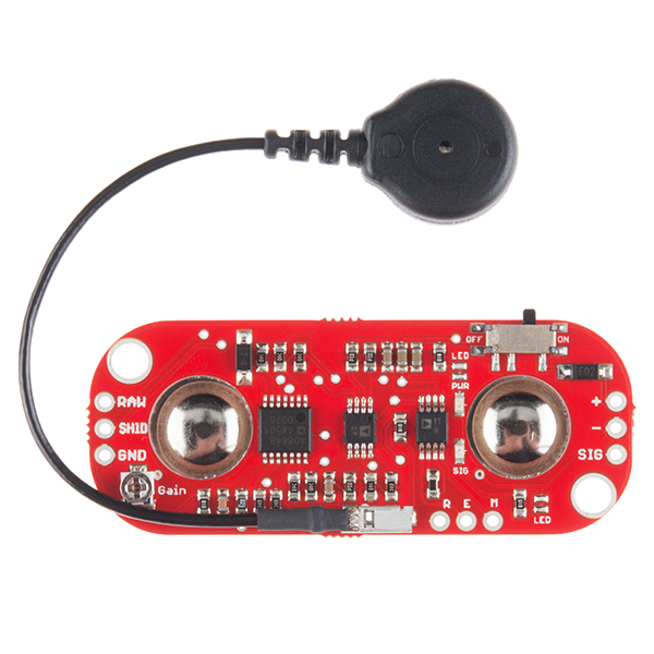
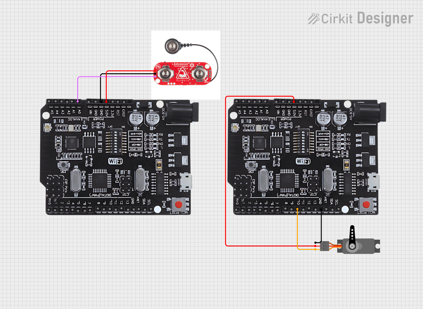
The MyoWare Muscle Sensor is a compact and versatile device designed to detect and measure the electrical activity of muscles, also known as electromyography (EMG) signals. This sensor is widely used in biomedical applications, such as monitoring muscle performance, controlling prosthetic devices, and creating interactive projects that respond to muscle activity. Its ease of use and compatibility with microcontrollers like Arduino make it a popular choice for hobbyists, researchers, and developers.
Explore Projects Built with Muscle Sensor
Explore Projects Built with Muscle Sensor
Common Applications and Use Cases
- Biomedical research and muscle activity monitoring
- Prosthetic control systems
- Gesture-based control interfaces
- Interactive robotics and wearable technology
- Physical therapy and rehabilitation devices
Technical Specifications
The MyoWare Muscle Sensor is designed to provide reliable and accurate EMG signal readings. Below are its key technical specifications:
| Parameter | Value |
|---|---|
| Operating Voltage | 3.1V to 5.5V |
| Operating Current | ~9mA |
| Output Voltage Range | 0V to Vcc (typically 3.3V or 5V) |
| Gain | Adjustable (default: 1000x) |
| Input Impedance | >1MΩ |
| Electrode Connector | Snap-style for standard electrodes |
| Dimensions | 1.0" x 1.0" (25.4mm x 25.4mm) |
Pin Configuration and Descriptions
The MyoWare Muscle Sensor has the following pin layout:
| Pin | Name | Description |
|---|---|---|
| 1 | VIN | Power input (3.1V to 5.5V). Connect to the power supply of your microcontroller. |
| 2 | GND | Ground connection. Connect to the ground of your circuit. |
| 3 | SIG | Signal output. Provides the processed EMG signal as an analog voltage. |
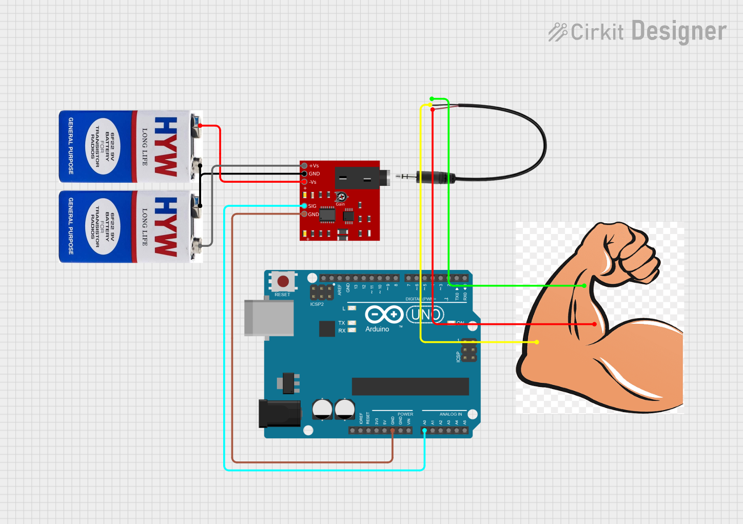
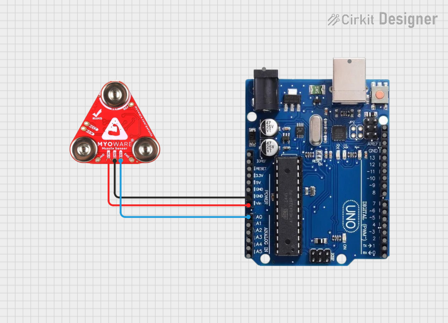
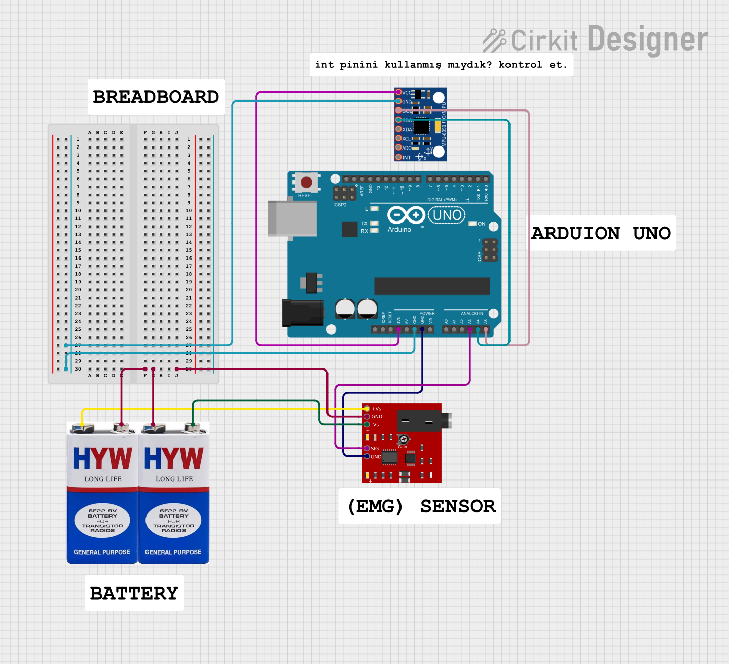
Usage Instructions
How to Use the Component in a Circuit
- Power the Sensor: Connect the VIN pin to a 3.3V or 5V power source and the GND pin to the ground of your circuit.
- Attach Electrodes: Snap three standard EMG electrodes to the sensor. Place the electrodes on the target muscle:
- Two electrodes should be placed on the muscle (aligned with the muscle fibers).
- The third electrode (reference) should be placed on a bony or non-muscular area.
- Connect the Signal Output: Connect the SIG pin to an analog input pin on your microcontroller (e.g., Arduino).
- Read the Signal: Use the microcontroller to read the analog voltage from the SIG pin. The voltage corresponds to the muscle activity level.
Important Considerations and Best Practices
- Electrode Placement: Proper placement of electrodes is critical for accurate readings. Ensure the skin is clean and dry before attaching electrodes.
- Power Supply: Use a stable power source to avoid noise in the signal.
- Signal Filtering: The output signal may require additional filtering or processing, depending on your application.
- Avoid Noise Sources: Keep the sensor and electrodes away from electrical noise sources, such as motors or high-frequency devices.
Example Code for Arduino UNO
The following code demonstrates how to read the MyoWare Muscle Sensor's output using an Arduino UNO and display the readings in the Serial Monitor:
// Define the analog pin connected to the SIG pin of the MyoWare Muscle Sensor
const int muscleSensorPin = A0;

void setup() {
  // Initialize the Serial Monitor for debugging
  Serial.begin(9600);
}

void loop() {
  // Read the analog value from the muscle sensor
  int sensorValue = analogRead(muscleSensorPin);

  // Convert the analog value to a voltage (assuming 5V reference)
  float voltage = sensorValue * (5.0 / 1023.0);

  // Print the voltage to the Serial Monitor
  Serial.print("Muscle Sensor Voltage: ");
  Serial.print(voltage);
  Serial.println(" V");

  // Add a small delay to stabilize readings
  delay(100);
}
Troubleshooting and FAQs
Common Issues and Solutions
No Signal or Low Signal Output:
- Ensure the electrodes are properly attached to the skin and the sensor.
- Check that the skin is clean and free of oils or moisture.
- Verify that the sensor is powered correctly (3.1V to 5.5V).
Noisy or Unstable Signal:
- Ensure the sensor and electrodes are not near electrical noise sources.
- Use shielded cables for connections if possible.
- Add a capacitor or low-pass filter to smooth the signal.
Incorrect Readings:
- Verify the electrode placement. Ensure the reference electrode is on a non-muscular area.
- Check the microcontroller's analog reference voltage settings.
FAQs
Q: Can I use the MyoWare Muscle Sensor with a 3.3V microcontroller?
A: Yes, the sensor operates within a voltage range of 3.1V to 5.5V, making it compatible with 3.3V systems.
Q: How do I clean the electrodes?
A: The electrodes are typically disposable. For reusable electrodes, follow the manufacturer's cleaning instructions.
Q: Can I use the sensor for long-term monitoring?
A: While the sensor can be used for extended periods, ensure the electrodes are replaced as needed and the skin is not irritated.
Q: Is additional signal processing required?
A: The sensor provides a pre-processed signal, but additional filtering or amplification may be needed depending on your application.