How to Use EM 18: Examples, Pinouts, and Specs
Introduction
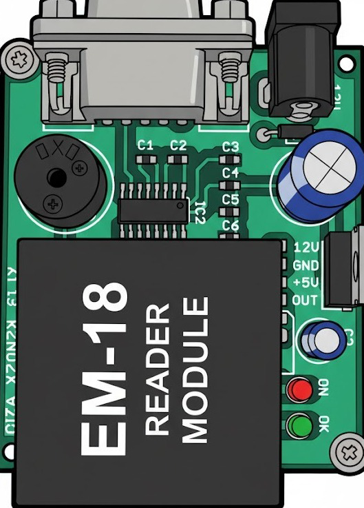
The EM 18 is an electromagnetic proximity sensor designed for detecting the presence of objects without requiring physical contact. Manufactured by READER MODULE, this sensor operates by emitting an electromagnetic field and detecting changes in that field caused by nearby metallic objects. It is widely used in applications requiring object detection, identification, and access control.
Explore Projects Built with EM 18
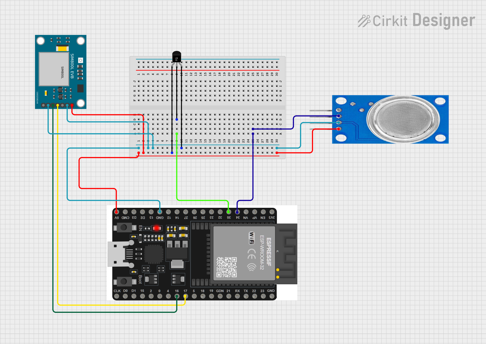
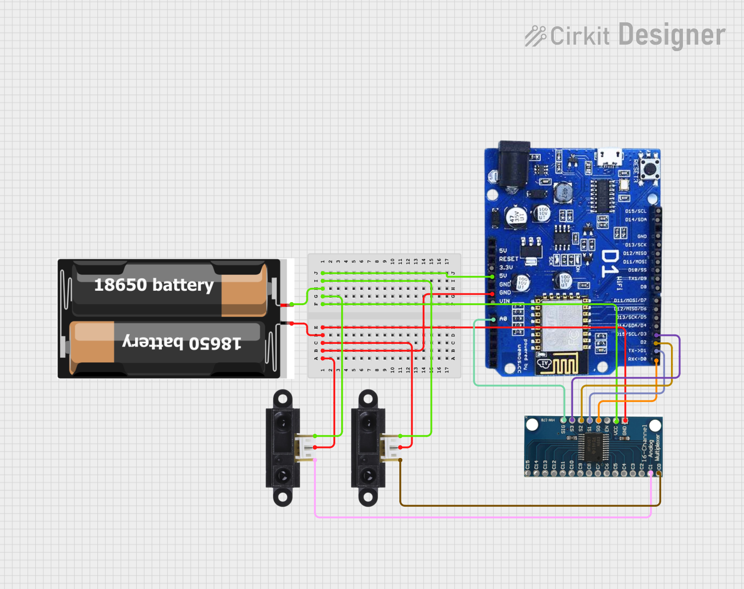

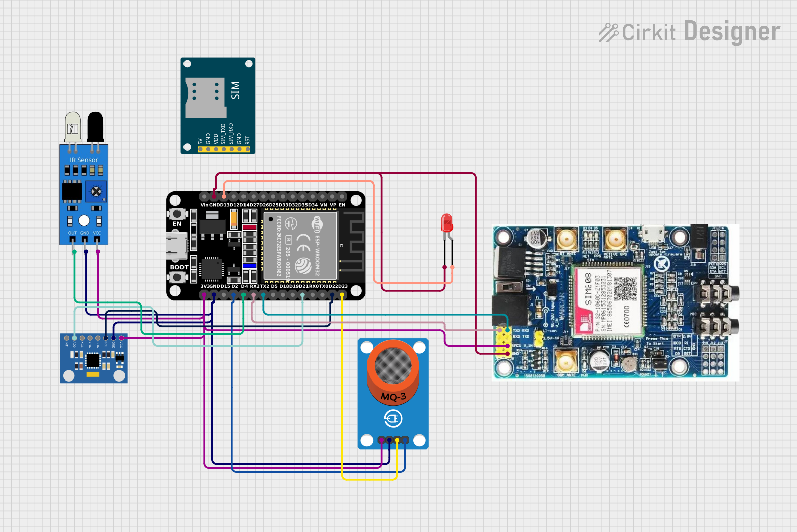
Explore Projects Built with EM 18
Common Applications and Use Cases
- RFID-based access control systems
- Inventory management and tracking
- Attendance systems
- Industrial automation for object detection
- Security systems for proximity-based authentication
Technical Specifications
The EM 18 is a robust and reliable sensor with the following key technical specifications:
| Parameter | Value |
|---|---|
| Operating Voltage | 5V DC |
| Operating Current | 50mA (typical) |
| Frequency | 125 kHz |
| Communication Protocol | UART (9600 bps) or Wiegand |
| Detection Range | Up to 10 cm (depending on tag type) |
| Dimensions | 32mm x 32mm x 8mm |
| Operating Temperature | -10°C to +70°C |
Pin Configuration and Descriptions
The EM 18 module has a simple pinout for easy integration into circuits. Below is the pin configuration:
| Pin | Name | Description |
|---|---|---|
| 1 | VCC | Power supply input (5V DC) |
| 2 | GND | Ground connection |
| 3 | TX | UART Transmit pin for serial communication |
| 4 | RX | UART Receive pin (not commonly used in standard applications) |
| 5 | BEEP | Output pin for connecting an external buzzer (optional) |
| 6 | LED | Output pin for connecting an external LED to indicate tag detection (optional) |
Usage Instructions
The EM 18 is straightforward to use in a variety of circuits. Below are the steps and considerations for using the module effectively:
Connecting the EM 18 to a Circuit
- Power Supply: Connect the VCC pin to a 5V DC power source and the GND pin to the ground.
- Data Communication: Use the TX pin to send data to a microcontroller or computer via UART. The RX pin is rarely used.
- Optional Outputs: Connect the BEEP and LED pins to external components if you want additional feedback for tag detection.
Interfacing with an Arduino UNO
The EM 18 can be easily interfaced with an Arduino UNO for RFID-based applications. Below is an example code snippet to read RFID tag data:
// Example code to interface EM 18 with Arduino UNO
// This code reads RFID tag data and displays it on the Serial Monitor

#include <SoftwareSerial.h>

// Define the RX and TX pins for SoftwareSerial
SoftwareSerial RFID(2, 3); // RX = Pin 2, TX = Pin 3

void setup() {
  Serial.begin(9600);       // Initialize Serial Monitor at 9600 bps
  RFID.begin(9600);         // Initialize EM 18 communication at 9600 bps
  Serial.println("EM 18 RFID Reader Initialized");
}

void loop() {
  if (RFID.available()) {   // Check if data is available from EM 18
    String tagData = "";    // Variable to store the RFID tag data
    while (RFID.available()) {
      char c = RFID.read(); // Read each character from EM 18
      tagData += c;         // Append character to tagData
    }
    Serial.print("RFID Tag Detected: ");
    Serial.println(tagData); // Print the tag data to Serial Monitor
  }
}
Important Considerations and Best Practices
- Ensure the power supply is stable and within the specified range (5V DC).
- Keep the detection area free from interference caused by other electromagnetic devices.
- Use proper pull-up resistors if required for external components like LEDs or buzzers.
- Avoid exposing the module to extreme temperatures or moisture to ensure longevity.
Troubleshooting and FAQs
Common Issues and Solutions
| Issue | Possible Cause | Solution |
|---|---|---|
| No data received from the module | Incorrect wiring or loose connections | Verify all connections, especially the TX pin to the microcontroller. |
| Detection range is too short | Interference or low-quality RFID tags | Use high-quality RFID tags and ensure no interference in the detection area. |
| Module not powering on | Insufficient power supply | Ensure a stable 5V DC power source is connected to the VCC pin. |
| Data is garbled or unreadable | Incorrect baud rate configuration | Set the UART baud rate to 9600 bps in your microcontroller or software. |
FAQs
Can the EM 18 detect non-metallic objects?
No, the EM 18 is designed to detect RFID tags, which typically contain metallic components.What is the maximum detection range of the EM 18?
The detection range is up to 10 cm, depending on the type and quality of the RFID tag.Can I use the EM 18 with a 3.3V microcontroller?
The EM 18 requires a 5V power supply. Use a level shifter to interface with 3.3V microcontrollers.How do I know if the module is working?
The onboard LED will blink when an RFID tag is detected, and data will be sent via the TX pin.
By following this documentation, users can effectively integrate and troubleshoot the EM 18 module in their projects.