How to Use Charge Controller: Examples, Pinouts, and Specs
Introduction
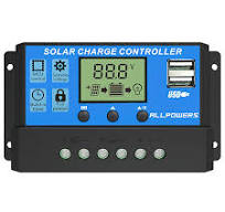
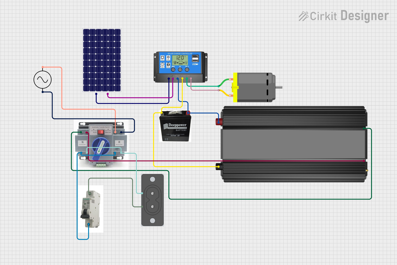
A charge controller is a vital component in solar power systems, designed to regulate the flow of electricity from the solar panels to the battery bank. Its primary function is to maintain the batteries at full charge without overcharging or deep discharging, which can significantly reduce the lifespan of the batteries. Charge controllers are used in various applications, including residential solar systems, remote telecommunications equipment, and RVs.
Explore Projects Built with Charge Controller
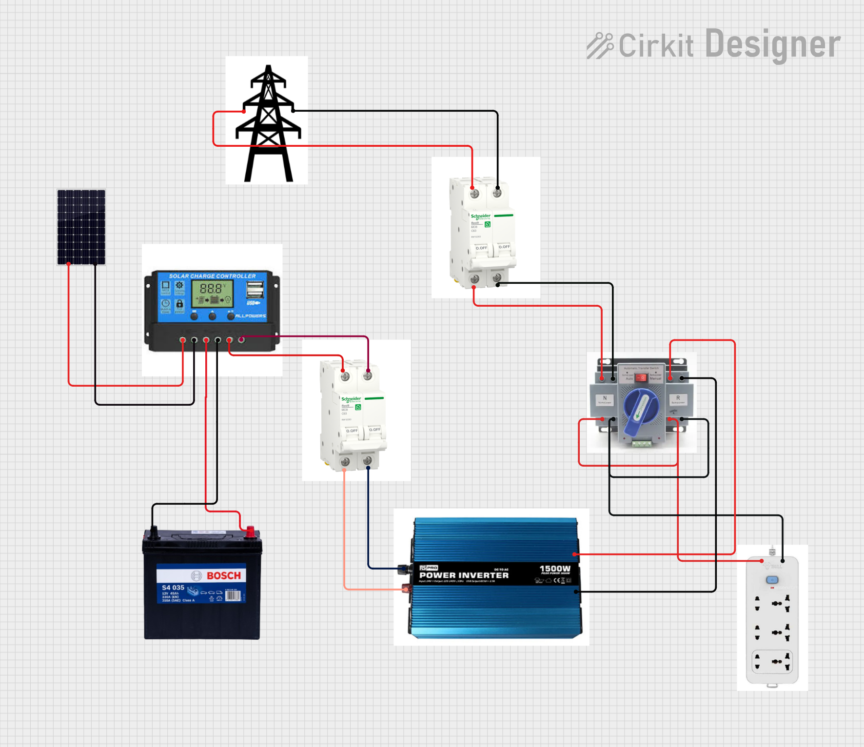
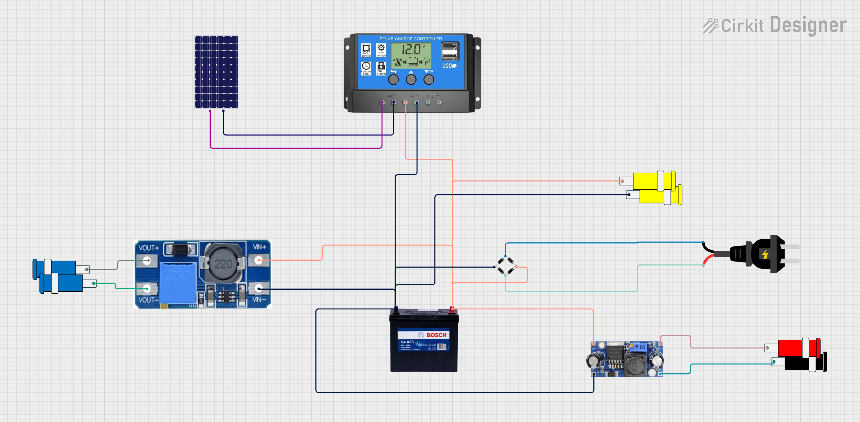
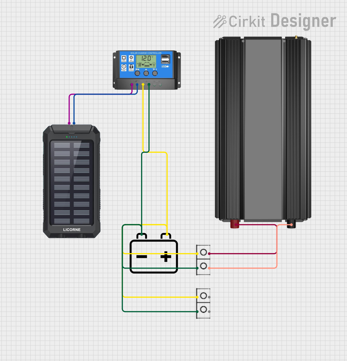
Explore Projects Built with Charge Controller
Technical Specifications
Key Technical Details
- Rated Voltage: Typically 12V, 24V, or 48V systems
- Maximum Current: Varies by model (e.g., 10A, 20A, 30A, etc.)
- Charging Algorithm: PWM (Pulse Width Modulation) or MPPT (Maximum Power Point Tracking)
- Temperature Compensation: Often included to adjust charging parameters with temperature
- Efficiency: Varies with technology, MPPT is generally more efficient than PWM
Pin Configuration and Descriptions
| Pin Number | Function | Description |
|---|---|---|
| 1 | Solar Panel (+) | Positive terminal for solar panel input |
| 2 | Solar Panel (-) | Negative terminal for solar panel input |
| 3 | Battery (+) | Positive terminal for battery connection |
| 4 | Battery (-) | Negative terminal for battery connection |
| 5 | Load (+) | Positive terminal for connecting loads (optional in some models) |
| 6 | Load (-) | Negative terminal for connecting loads (optional in some models) |
| 7 | Temperature Sensor | Connection for external temperature sensor (if applicable) |
| 8 | Remote Monitoring | Port for remote monitoring and control (if applicable) |
Usage Instructions
Connecting the Charge Controller
- Safety First: Ensure all power sources are disconnected before making any connections.
- Connect the Battery: Attach the battery cables to the charge controller's battery terminals, ensuring correct polarity.
- Connect the Solar Panels: With the battery connected, attach the solar panel cables to the solar panel terminals on the charge controller.
- Connect the Load (if applicable): Some charge controllers allow you to connect loads directly. Connect the load cables to the load terminals.
Best Practices
- Use Appropriate Wire Sizes: To minimize voltage drop and prevent overheating, use the correct gauge of wire for your system's current and distance.
- Install Fuses/Circuit Breakers: Protect your system by installing appropriate fuses or circuit breakers on the positive lines between the solar panels, charge controller, and battery.
- Regular Maintenance: Check connections for corrosion or looseness and clean the solar panels regularly for optimal performance.
Troubleshooting and FAQs
Common Issues
- Battery Not Charging: Ensure all connections are secure and the solar panels are receiving sunlight. Check for any blown fuses or tripped breakers.
- Overcharging Battery: This could indicate a malfunctioning charge controller. Verify the settings and replace the controller if necessary.
- Controller Not Turning On: Check the battery voltage to ensure it's within the operating range of the controller. Inspect for any loose connections or damage.
FAQs
Q: Can I use a 24V charge controller with a 12V battery? A: No, the voltage rating of the charge controller must match the voltage of the battery bank.
Q: How do I know if my charge controller is MPPT or PWM? A: This information is typically found in the product specifications or on the label of the charge controller.
Q: What size charge controller do I need? A: The size of the charge controller is determined by the current produced by your solar panels and the voltage of your battery bank. A general rule of thumb is to take the solar panel wattage, divide by the battery voltage, and add 25% for a safety margin.
Q: Can I connect a wind turbine to my solar charge controller? A: No, wind turbines require a specific type of charge controller designed for the variable voltage and current they produce.
Example Arduino Code for Monitoring
// Example code for monitoring charge controller parameters via Arduino UNO
// Ensure your charge controller has a communication port and is compatible with Arduino.

#include <SoftwareSerial.h>

SoftwareSerial chargeControllerSerial(10, 11); // RX, TX

void setup() {
  Serial.begin(9600);
  chargeControllerSerial.begin(9600);
  // Initialize communication with charge controller
}

void loop() {
  if (chargeControllerSerial.available()) {
    // Read data from charge controller
    String data = chargeControllerSerial.readStringUntil('\n');
    Serial.println(data); // Output the data to the serial monitor
  }
  // Add code here to process and display the data as needed
  delay(1000); // Wait for a second before reading again
}
Note: The above code is a simple example to illustrate how you might begin to interface with a charge controller that has serial communication capabilities. The actual implementation will vary based on the specific model and communication protocol of your charge controller. Always refer to the manufacturer's documentation for the correct communication methods and data interpretation.