How to Use Adafruit PA1010D Mini GPS Module: Examples, Pinouts, and Specs
Introduction
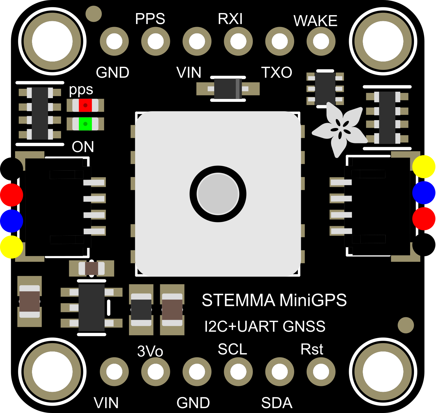
The Adafruit PA1010D Mini GPS Module is a compact, high-performance GPS receiver with an integrated antenna and built-in data logging capabilities. It utilizes the MTK3333 chipset capable of tracking up to 33 satellites on 99 channels. This module is ideal for a wide range of applications including asset tracking, navigation, and time synchronization.
Explore Projects Built with Adafruit PA1010D Mini GPS Module
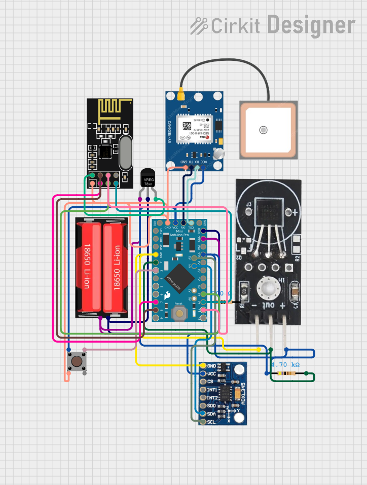
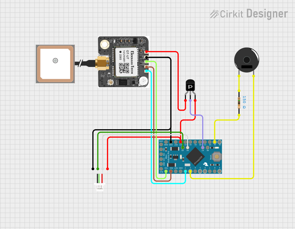

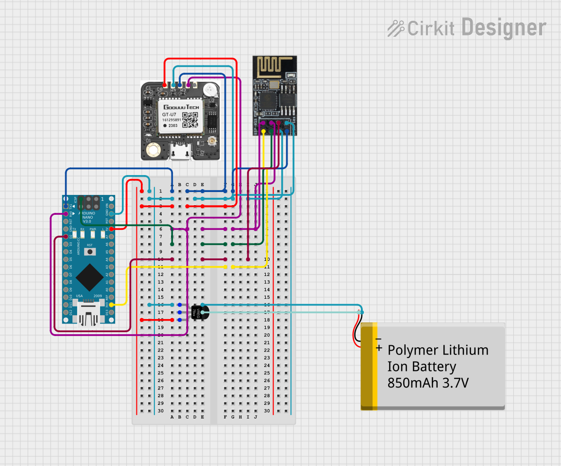
Explore Projects Built with Adafruit PA1010D Mini GPS Module
Common Applications and Use Cases
- Personal and asset tracking devices
- Data logging and geotagging
- Time synchronization for systems
- Navigation aids for drones and remote-controlled vehicles
- Location-based projects and services
Technical Specifications
Key Technical Details
- Chipset: MediaTek MT3333
- Channels: 99 tracking, 33 acquisition
- Update Rate: Up to 10 Hz
- Sensitivity: -165 dBm
- Horizontal Position Accuracy: < 3m (50% CEP)
- Operating Voltage: 3.0V to 5.5V
- Operating Current: 25 mA tracking, 20 mA current draw during navigation
- Operating Temperature: -40°C to 85°C
Pin Configuration and Descriptions
| Pin Number | Name | Description |
|---|---|---|
| 1 | GND | Ground connection |
| 2 | VIN | Power supply input (3.0V to 5.5V) |
| 3 | TX | Transmit pin for serial communication |
| 4 | RX | Receive pin for serial communication |
| 5 | PPS | Pulse Per Second, timing signal output |
| 6 | EN | Enable pin, active high |
Usage Instructions
How to Use the Component in a Circuit
- Power Supply: Connect the VIN pin to a 3.0V to 5.5V power source and the GND pin to the ground.
- Serial Communication: Connect the TX pin of the GPS module to the RX pin of your microcontroller and the RX pin to the TX pin.
- PPS Signal: The PPS pin can be connected to an interrupt pin on your microcontroller if you require precise timing.
- Enable Pin: The EN pin can be left unconnected for normal operation or connected to a digital pin on your microcontroller to control the power state of the module.
Important Considerations and Best Practices
- Ensure that the GPS module has a clear view of the sky for optimal performance.
- Avoid placing the module near devices that emit RF noise, as this can interfere with signal reception.
- Use a level shifter if you are interfacing with a microcontroller that operates at a different logic level than the GPS module.
- For data logging, make sure to have a battery connected to the VBAT pin to keep the real-time clock running.
Example Code for Arduino UNO
#include <SoftwareSerial.h>

// Define the RX and TX pins connected to the GPS module
#define GPS_RX_PIN 3
#define GPS_TX_PIN 4

// Set up the software serial port
SoftwareSerial gpsSerial(GPS_RX_PIN, GPS_TX_PIN);

void setup() {
  // Start the serial communication with the host computer
  Serial.begin(9600);
  // Start the serial communication with the GPS module
  gpsSerial.begin(9600);
}

void loop() {
  // Check if new data is available from the GPS module
  if (gpsSerial.available()) {
    // Read the data and print it to the host computer's serial monitor
    Serial.write(gpsSerial.read());
  }
}
Troubleshooting and FAQs
Common Issues Users Might Face
- No GPS Fix: Ensure the module has a clear view of the sky and that it is not obstructed by buildings or other structures.
- Garbled Data: Check the baud rate settings and wiring connections between the GPS module and your microcontroller.
- Module Not Powering Up: Verify that the power supply is within the specified voltage range and that the connections are secure.
Solutions and Tips for Troubleshooting
- No GPS Fix: If you're indoors or in a dense urban area, try moving to a location with a clearer view of the sky.
- Garbled Data: Double-check the serial communication baud rate and ensure it matches the default rate of the GPS module.
- Module Not Powering Up: Check the power supply with a multimeter and inspect the solder joints for any cold solder or breaks.
FAQs
Q: How long does it take for the PA1010D to get a GPS fix? A: The time to first fix (TTFF) can vary, but typically it takes about 30 seconds with a clear sky view.
Q: Can I use the PA1010D with a 3.3V microcontroller? A: Yes, the PA1010D can be powered with 3.3V and is compatible with 3.3V logic levels.
Q: What is the purpose of the PPS pin? A: The PPS pin outputs a pulse per second, which can be used for precise timing applications.
Q: How can I improve the GPS signal reception? A: Ensure the module's antenna has an unobstructed view of the sky and is placed away from electronic interference sources.