Cirkit Designer LogoCirkit DesignerYour all-in-one circuit design IDE Launch Cirkit Designer App

How to Use MQ-9: Examples, Pinouts, and Specs

Image of MQ-9Design with MQ-9 in Cirkit Designer

Introduction

Explore Projects Built with MQ-9

Use Cirkit Designer to design, explore, and prototype these projects online. Some projects support real-time simulation. Click "Open Project" to start designing instantly!
Image of Arduino UNO and A9G GSM/GPRS GPS-Based Air Quality Monitoring System: A project utilizing MQ-9 in a practical application

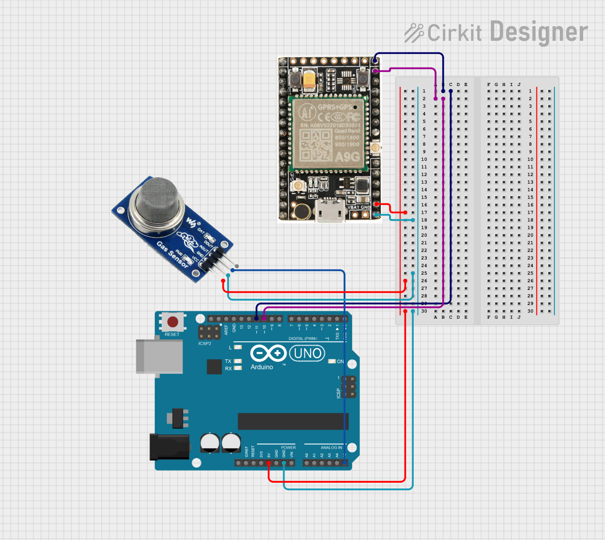
Arduino UNO and A9G GSM/GPRS GPS-Based Air Quality Monitoring System

This circuit features an Arduino UNO microcontroller interfaced with an A9G GSM/GPRS+GPS module and an MQ2 gas sensor. The Arduino communicates with the A9G module via digital pins D11 and D10 for data transmission, and it reads analog gas concentration levels from the MQ2 sensor through analog pin A5. Both the A9G module and the MQ2 sensor are powered by the Arduino's 5V output, and all components share a common ground.

Open Project in Cirkit Designer
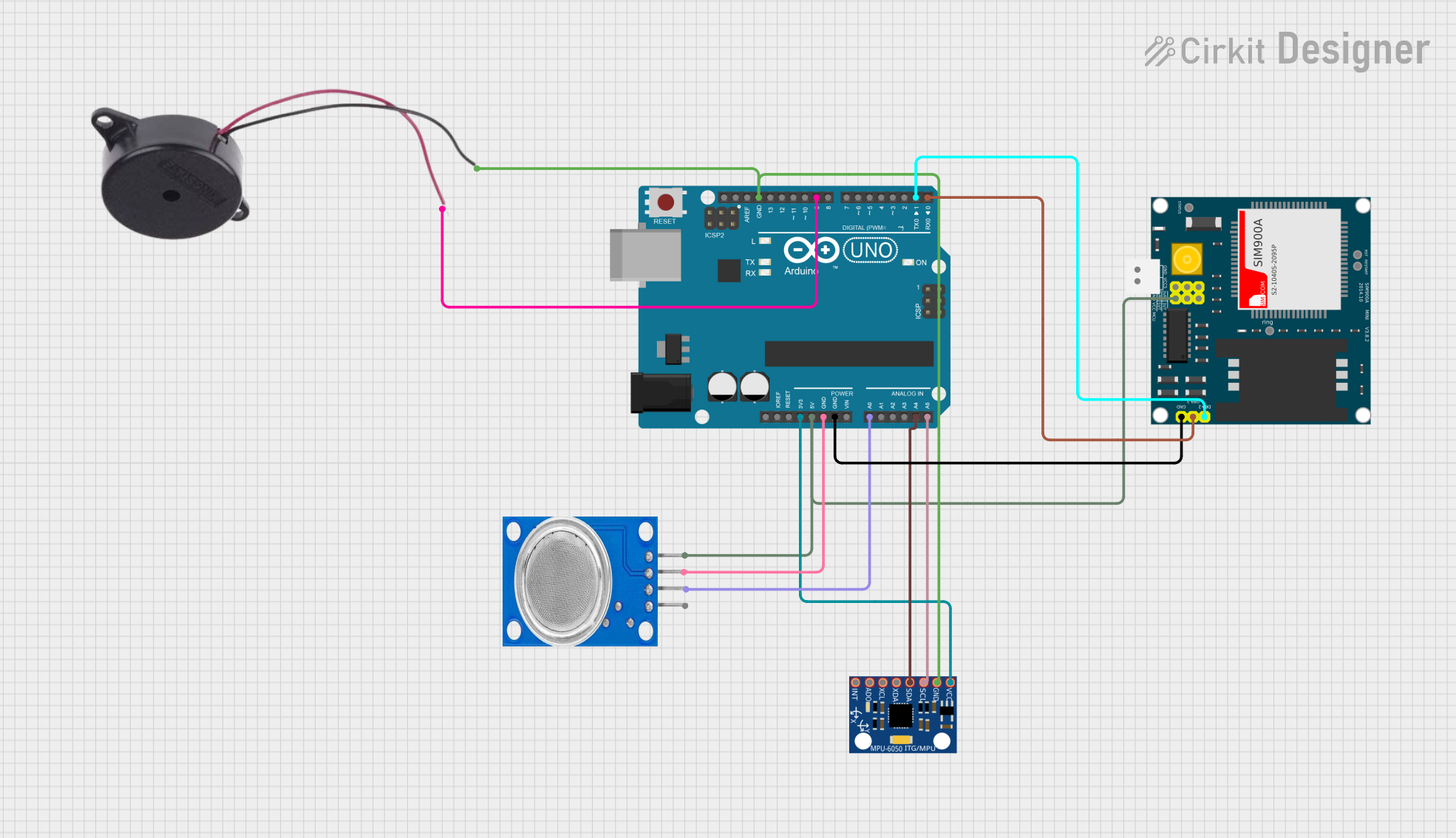
Image of Arduino UNO Based Air Quality Monitoring and GSM Notification System: A project utilizing MQ-9 in a practical application
Arduino UNO Based Air Quality Monitoring and GSM Notification System

This circuit features an Arduino UNO microcontroller interfaced with an MQ135 air quality sensor, an MPU-6050 accelerometer/gyroscope, a SIM900A GSM communication module, and a buzzer. The Arduino reads analog data from the MQ135 sensor and communicates with the MPU-6050 via I2C, while also controlling the buzzer and handling serial communication with the SIM900A module. The purpose of this circuit is likely to monitor air quality and motion, provide alerts through the buzzer, and enable remote communication via GSM.

Open Project in Cirkit Designer

Technical Specifications

Pin Configuration and Descriptions

Pin Name Pin Number Description
VCC 1 Power supply input (5V DC)
GND 2 Ground connection
AOUT 3 Analog output signal proportional to gas concentration
DOUT 4 Digital output signal (high/low) based on a user-defined threshold

Usage Instructions

How to Use the MQ-9 in a Circuit

  1. Power Supply: Connect the VCC pin to a 5V DC power source and the GND pin to the ground.
  2. Signal Output:
    • Use the AOUT pin to read the analog signal for precise gas concentration measurements.
    • Use the DOUT pin for a simple high/low signal based on a preset threshold (adjustable via the onboard potentiometer).
  3. Preheating: Allow the sensor to preheat for at least 24 hours before taking accurate measurements.
  4. Connection to Microcontroller:
    • Connect the AOUT pin to an analog input pin of a microcontroller (e.g., Arduino UNO).
    • Optionally, connect the DOUT pin to a digital input pin for threshold-based detection.

Important Considerations and Best Practices

Example Code for Arduino UNO

// MQ-9 Gas Sensor Example Code for Arduino UNO
// This code reads analog data from the MQ-9 sensor and prints the gas concentration
// to the Serial Monitor. Ensure the sensor is connected to the correct pins.

const int analogPin = A0; // Connect AOUT pin of MQ-9 to Arduino analog pin A0
const int digitalPin = 2; // Connect DOUT pin of MQ-9 to Arduino digital pin 2

void setup() {
  Serial.begin(9600); // Initialize serial communication at 9600 baud
  pinMode(digitalPin, INPUT); // Set DOUT pin as input
}

void loop() {
  int analogValue = analogRead(analogPin); // Read analog value from AOUT
  int digitalValue = digitalRead(digitalPin); // Read digital value from DOUT

  // Convert analog value to voltage (assuming 5V reference)
  float voltage = analogValue * (5.0 / 1023.0);

  // Print the readings to the Serial Monitor
  Serial.print("Analog Value: ");
  Serial.print(analogValue);
  Serial.print(" | Voltage: ");
  Serial.print(voltage);
  Serial.print("V | Digital Value: ");
  Serial.println(digitalValue);

  delay(1000); // Wait for 1 second before the next reading
}

Troubleshooting and FAQs

Common Issues

  1. No Output Signal:
    • Ensure the sensor is properly connected to the power supply and ground.
    • Verify that the preheat time has been completed (≥ 24 hours).
  2. Inaccurate Readings:
    • Check for proper calibration in a clean air environment.
    • Ensure the sensor is not exposed to extreme temperatures or humidity.
  3. Digital Output Always High/Low:
    • Adjust the onboard potentiometer to set an appropriate threshold for the DOUT signal.

Solutions and Tips for Troubleshooting

By following this documentation, users can effectively integrate the MQ-9 Gas Sensor Module into their projects and ensure reliable gas detection performance.