Cirkit Designer Logo
Cirkit Designer
Your all-in-one circuit design IDE
Home / 
Component Documentation

How to Use ML8511 Breakout Board: Examples, Pinouts, and Specs

Image of ML8511 Breakout Board
Cirkit Designer LogoDesign with ML8511 Breakout Board in Cirkit Designer

Introduction

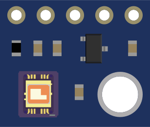
The ML8511 Breakout Board is a compact and easy-to-use module designed for the ML8511 UV sensor. This sensor is capable of detecting ultraviolet (UV) light, which is commonly found in sunlight. The ML8511 sensor is sensitive to UV-A and UV-B wavelengths, which are the types of UV radiation most relevant for applications such as monitoring UV exposure for health and safety, UV index monitoring for weather stations, and testing UV-blocking materials.

Explore Projects Built with ML8511 Breakout Board

Use Cirkit Designer to design, explore, and prototype these projects online. Some projects support real-time simulation. Click "Open Project" to start designing instantly!
Lilygo 7670e-Based Smart Interface with LCD Display and Keypad
Image of Paower: A project utilizing ML8511 Breakout Board in a practical application
This circuit features a Lilygo 7670e microcontroller interfaced with a 16x2 I2C LCD for display, a 4X4 membrane matrix keypad for input, and an arcade button for additional control. It also includes a 4G antenna and a GPS antenna for communication and location tracking capabilities.
Cirkit Designer LogoOpen Project in Cirkit Designer
Cellular-Enabled IoT Device with Real-Time Clock and Power Management
Image of LRCM PHASE 2 BASIC: A project utilizing ML8511 Breakout Board in a practical application
This circuit features a LilyGo-SIM7000G module for cellular communication and GPS functionality, interfaced with an RTC DS3231 for real-time clock capabilities. It includes voltage sensing through two voltage sensor modules, and uses an 8-channel opto-coupler for isolating different parts of the circuit. Power management is handled by a buck converter connected to a DC power source and batteries, with a fuse for protection and a rocker switch for on/off control. Additionally, there's an LED for indication purposes.
Cirkit Designer LogoOpen Project in Cirkit Designer
MakerEdu Creator with Bluetooth, IR Sensors, LCD Display, and Push Button Interaction
Image of MKL Distance Measurement: A project utilizing ML8511 Breakout Board in a practical application
This circuit features a MakerEdu Creator microcontroller board interfaced with two MKE-S11 IR Infrared Obstacle Avoidance Sensors, a MKE-M02 Push Button Tact Switch, a MKE-M15 Bluetooth module, and a MKE-M08 LCD2004 I2C display module. The push button is connected to a digital input for user interaction, while the IR sensors are likely used for detecting obstacles. The Bluetooth module enables wireless communication, and the LCD display provides a user interface for displaying information or statuses.
Cirkit Designer LogoOpen Project in Cirkit Designer
Arduino 101 Based Access Control System with RFID and Keypad
Image of door1: A project utilizing ML8511 Breakout Board in a practical application
This circuit features an Arduino 101 microcontroller connected to a variety of peripherals. An LCD screen is interfaced via I2C for display, an RFID-RC522 module is connected for RFID reading capabilities, and two SG90 servomotors are controlled by the Arduino. Additionally, a 4x4 membrane matrix keypad is used for input, and a buzzer is included for audio feedback, all powered through a breadboard power module supplying 5V or 3.3V as needed.
Cirkit Designer LogoOpen Project in Cirkit Designer

Explore Projects Built with ML8511 Breakout Board

Use Cirkit Designer to design, explore, and prototype these projects online. Some projects support real-time simulation. Click "Open Project" to start designing instantly!
Image of Paower: A project utilizing ML8511 Breakout Board in a practical application
Lilygo 7670e-Based Smart Interface with LCD Display and Keypad
This circuit features a Lilygo 7670e microcontroller interfaced with a 16x2 I2C LCD for display, a 4X4 membrane matrix keypad for input, and an arcade button for additional control. It also includes a 4G antenna and a GPS antenna for communication and location tracking capabilities.
Cirkit Designer LogoOpen Project in Cirkit Designer
Image of LRCM PHASE 2 BASIC: A project utilizing ML8511 Breakout Board in a practical application
Cellular-Enabled IoT Device with Real-Time Clock and Power Management
This circuit features a LilyGo-SIM7000G module for cellular communication and GPS functionality, interfaced with an RTC DS3231 for real-time clock capabilities. It includes voltage sensing through two voltage sensor modules, and uses an 8-channel opto-coupler for isolating different parts of the circuit. Power management is handled by a buck converter connected to a DC power source and batteries, with a fuse for protection and a rocker switch for on/off control. Additionally, there's an LED for indication purposes.
Cirkit Designer LogoOpen Project in Cirkit Designer
Image of MKL Distance Measurement: A project utilizing ML8511 Breakout Board in a practical application
MakerEdu Creator with Bluetooth, IR Sensors, LCD Display, and Push Button Interaction
This circuit features a MakerEdu Creator microcontroller board interfaced with two MKE-S11 IR Infrared Obstacle Avoidance Sensors, a MKE-M02 Push Button Tact Switch, a MKE-M15 Bluetooth module, and a MKE-M08 LCD2004 I2C display module. The push button is connected to a digital input for user interaction, while the IR sensors are likely used for detecting obstacles. The Bluetooth module enables wireless communication, and the LCD display provides a user interface for displaying information or statuses.
Cirkit Designer LogoOpen Project in Cirkit Designer
Image of door1: A project utilizing ML8511 Breakout Board in a practical application
Arduino 101 Based Access Control System with RFID and Keypad
This circuit features an Arduino 101 microcontroller connected to a variety of peripherals. An LCD screen is interfaced via I2C for display, an RFID-RC522 module is connected for RFID reading capabilities, and two SG90 servomotors are controlled by the Arduino. Additionally, a 4x4 membrane matrix keypad is used for input, and a buzzer is included for audio feedback, all powered through a breadboard power module supplying 5V or 3.3V as needed.
Cirkit Designer LogoOpen Project in Cirkit Designer

Common Applications and Use Cases

  • Personal UV exposure monitoring devices
  • Weather stations measuring UV index
  • Testing the effectiveness of UV-blocking films and coatings
  • Scientific experiments involving UV light
  • Industrial monitoring of UV curing processes

Technical Specifications

Key Technical Details

  • Operating Voltage: 2.7V to 5.5V
  • UV Wavelength Detection Range: 280nm to 390nm (UV-A and UV-B)
  • Output: Analog voltage proportional to UV light intensity
  • Response Time: Less than 0.5 seconds

Pin Configuration and Descriptions

Pin Number Name Description
1 EN Enable pin for the sensor (active high)
2 OUT Analog output voltage from the sensor
3 3V3 3.3V power supply input
4 GND Ground connection

Usage Instructions

How to Use the Component in a Circuit

  1. Powering the Sensor: Connect the 3V3 pin to a 3.3V supply on your microcontroller board, and the GND pin to the ground.

  2. Enabling the Sensor: The EN pin can be tied to the 3.3V supply if you want the sensor to be always on. If you wish to control the power state of the sensor, connect the EN pin to a digital output on your microcontroller.

  3. Reading the Sensor: Connect the OUT pin to an analog input on your microcontroller. The voltage read from this pin will be proportional to the UV light intensity.

Important Considerations and Best Practices

  • Calibration: The sensor output needs to be calibrated against a known UV light source to ensure accurate readings.
  • Voltage Levels: If you are using a microcontroller that operates at 5V, ensure that the analog input can handle the voltage range of the sensor output.
  • Ambient Light: The sensor is sensitive to ambient light; thus, it should be shielded from other light sources for accurate UV measurements.
  • Temperature Effects: The sensor's readings can be affected by temperature, so compensation may be necessary for precise applications.

Example Code for Arduino UNO

// ML8511 UV Sensor Example Code for Arduino UNO
int UVOUT = A0; // Output from the sensor
int REF_3V3 = A1; // 3.3V power on the Arduino board

void setup() {
  Serial.begin(9600);
}

void loop() {
  int uvLevel = averageAnalogRead(UVOUT);
  int refLevel = averageAnalogRead(REF_3V3);
  
  // Use the 3.3V power pin as a reference to get a very accurate output value from sensor
  float outputVoltage = 3.3 / refLevel * uvLevel;

  // Convert the voltage to a UV intensity level
  float uvIntensity = mapfloat(outputVoltage, 0.99, 2.9, 0.0, 15.0);

  Serial.print("UV Intensity (mW/cm^2): ");
  Serial.println(uvIntensity);

  delay(200);
}

// Takes an average of readings on a given analog input
int averageAnalogRead(int pinToRead) {
  byte numberOfReadings = 8;
  unsigned int runningValue = 0;

  for (int x = 0; x < numberOfReadings; x++)
    runningValue += analogRead(pinToRead);
  runningValue /= numberOfReadings;

  return runningValue;
}

// The Arduino Map function but for floats
float mapfloat(float x, float in_min, float in_max, float out_min, float out_max) {
  return (x - in_min) * (out_max - out_min) / (in_max - in_min) + out_min;
}

Troubleshooting and FAQs

Common Issues Users Might Face

  • Inaccurate Readings: Ensure the sensor is properly calibrated and not influenced by other light sources.
  • No Readings: Check the power supply and connections to the sensor. Ensure the EN pin is set high if controlled by the microcontroller.
  • Fluctuating Readings: Use capacitors to stabilize the power supply if necessary and consider averaging multiple readings for stability.

Solutions and Tips for Troubleshooting

  • Calibration: Use a known UV light source to calibrate the sensor's output.
  • Shielding: Shield the sensor from ambient light when measuring UV light.
  • Temperature Compensation: Implement temperature compensation in the code if precise measurements are required.

FAQs

Q: Can the ML8511 sensor detect UV-C light? A: No, the ML8511 is designed to detect UV-A and UV-B wavelengths, not UV-C.

Q: Is it necessary to use the EN pin? A: The EN pin is optional. If you do not need to control the power state of the sensor, you can tie it directly to the 3.3V supply.

Q: How can I improve the accuracy of the sensor? A: Calibration against a known UV light source and shielding from other light sources can improve accuracy. Additionally, averaging multiple readings can help reduce noise.