Cirkit Designer Logo
Cirkit Designer
Your all-in-one circuit design IDE
Home / 
Component Documentation

How to Use AD8232 HeartRate Monitor: Examples, Pinouts, and Specs

Image of AD8232 HeartRate Monitor
Cirkit Designer LogoDesign with AD8232 HeartRate Monitor in Cirkit Designer

Introduction

The AD8232 from Analog Devices is a dedicated single-lead heart rate monitor analog front end that is ideal for monitoring electrical activity of the heart. This small and power-efficient integrated circuit (IC) is optimized for wearable health monitoring devices and fitness trackers. It is capable of extracting, amplifying, and filtering small biopotential signals in the presence of noisy conditions, such as those created by motion or remote electrode placement.

Explore Projects Built with AD8232 HeartRate Monitor

Use Cirkit Designer to design, explore, and prototype these projects online. Some projects support real-time simulation. Click "Open Project" to start designing instantly!
Arduino Micro and AD8232 Heart Rate Monitor with Lead-Off Detection
Image of ecg : A project utilizing AD8232 HeartRate Monitor in a practical application
This circuit is a heart rate monitoring system that uses an AD8232 Heart Rate Monitor module connected to an Arduino Micro (Rev3). The Arduino reads the heart rate signal from the AD8232 and prints the analog values to the Serial Monitor, while also checking for lead-off detection.
Cirkit Designer LogoOpen Project in Cirkit Designer
ESP32-Powered Heart Rate Monitor with TFT Display and Battery Backup
Image of ECG 4: A project utilizing AD8232 HeartRate Monitor in a practical application
This circuit is a heart rate monitoring system that uses an AD8232 Heart Rate Monitor to capture heart rate signals, which are processed by an ESP32 microcontroller. The ESP32 displays the heart rate data on an ILI9341 TFT display and includes a push button for user interaction, powered by a 9V battery with a rocker switch for power control.
Cirkit Designer LogoOpen Project in Cirkit Designer
Arduino MKR WiFi 1010 Heart Rate Monitor with I2C LCD Display
Image of ECG circuit: A project utilizing AD8232 HeartRate Monitor in a practical application
This circuit is a heart rate monitoring system that uses an AD8232 Heart Rate Monitor to measure heart signals and an Arduino MKR WiFi 1010 to process the data. The processed heart rate data is then displayed on a 16x2 I2C LCD screen. Power is supplied by an external power supply.
Cirkit Designer LogoOpen Project in Cirkit Designer
ESP32-Based Battery-Powered Heart Rate Monitor with SD Card Storage
Image of ECG Recorder: A project utilizing AD8232 HeartRate Monitor in a practical application
This circuit is a portable heart rate monitoring system that uses an ESP32 microcontroller to read data from an AD8232 heart rate monitor and store it on an SD card module. The system is powered by a 3.7V LiPo battery with a TP4056 module for battery charging and protection.
Cirkit Designer LogoOpen Project in Cirkit Designer

Explore Projects Built with AD8232 HeartRate Monitor

Use Cirkit Designer to design, explore, and prototype these projects online. Some projects support real-time simulation. Click "Open Project" to start designing instantly!
Image of ecg : A project utilizing AD8232 HeartRate Monitor in a practical application
Arduino Micro and AD8232 Heart Rate Monitor with Lead-Off Detection
This circuit is a heart rate monitoring system that uses an AD8232 Heart Rate Monitor module connected to an Arduino Micro (Rev3). The Arduino reads the heart rate signal from the AD8232 and prints the analog values to the Serial Monitor, while also checking for lead-off detection.
Cirkit Designer LogoOpen Project in Cirkit Designer
Image of ECG 4: A project utilizing AD8232 HeartRate Monitor in a practical application
ESP32-Powered Heart Rate Monitor with TFT Display and Battery Backup
This circuit is a heart rate monitoring system that uses an AD8232 Heart Rate Monitor to capture heart rate signals, which are processed by an ESP32 microcontroller. The ESP32 displays the heart rate data on an ILI9341 TFT display and includes a push button for user interaction, powered by a 9V battery with a rocker switch for power control.
Cirkit Designer LogoOpen Project in Cirkit Designer
Image of ECG circuit: A project utilizing AD8232 HeartRate Monitor in a practical application
Arduino MKR WiFi 1010 Heart Rate Monitor with I2C LCD Display
This circuit is a heart rate monitoring system that uses an AD8232 Heart Rate Monitor to measure heart signals and an Arduino MKR WiFi 1010 to process the data. The processed heart rate data is then displayed on a 16x2 I2C LCD screen. Power is supplied by an external power supply.
Cirkit Designer LogoOpen Project in Cirkit Designer
Image of ECG Recorder: A project utilizing AD8232 HeartRate Monitor in a practical application
ESP32-Based Battery-Powered Heart Rate Monitor with SD Card Storage
This circuit is a portable heart rate monitoring system that uses an ESP32 microcontroller to read data from an AD8232 heart rate monitor and store it on an SD card module. The system is powered by a 3.7V LiPo battery with a TP4056 module for battery charging and protection.
Cirkit Designer LogoOpen Project in Cirkit Designer

Common Applications and Use Cases

  • Portable ECG monitors
  • Fitness and activity heart rate monitors
  • Biopotential signal acquisition systems
  • Wearable health monitoring devices

Technical Specifications

Key Technical Details

  • Supply Voltage: 2.0 V to 3.5 V
  • Operating Temperature: -40°C to +85°C
  • Shutdown Current: 50 nA (typical)
  • Gain: Adjustable with external resistor

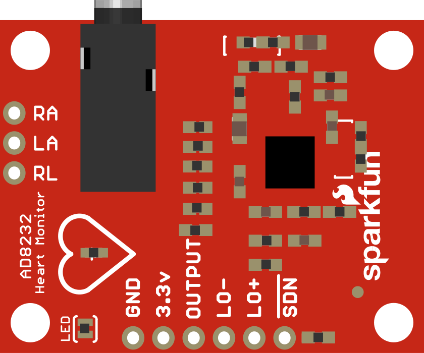
Pin Configuration and Descriptions

Pin Number Name Description
1 IN+ Positive input for the differential amplifier
2 IN- Negative input for the differential amplifier
3 SDN Shutdown pin; active low
4 GND Ground reference for the circuit
5 OUTPUT Output signal of the heart rate monitor
6 LO+ Lead-off detection positive input
7 LO- Lead-off detection negative input
8 VCC Supply voltage for the IC

Usage Instructions

How to Use the Component in a Circuit

  1. Power Supply: Connect the VCC pin to a 2.0 V to 3.5 V power source and the GND pin to the ground of your system.
  2. Input Connections: Attach the IN+ and IN- pins to the biopotential electrodes placed on the body.
  3. Output Signal: Connect the OUTPUT pin to an analog-to-digital converter (ADC) or microcontroller to process the heart rate signal.
  4. Shutdown Control: The SDN pin can be connected to a digital output of a microcontroller to put the IC into a low power state when not in use.
  5. Lead-Off Detection: Connect LO+ and LO- to the system to detect when the electrodes have become disconnected from the user.

Important Considerations and Best Practices

  • Use proper shielding and grounding to minimize noise.
  • Keep the leads to the electrodes as short as possible to reduce artifacts.
  • Avoid placing the electrodes near muscles to minimize EMG signals.
  • Ensure that the power supply is stable and within the specified voltage range.

Troubleshooting and FAQs

Common Issues Users Might Face

  • Noisy Signal: Ensure that the electrodes are properly attached and that the leads are not picking up interference from other electronic devices.
  • Weak Signal: Check that the electrodes are making good contact with the skin and that the skin is clean before electrode placement.
  • Device Not Powering On: Verify that the power supply is within the specified range and that all connections are secure.

Solutions and Tips for Troubleshooting

  • If the signal is noisy, try repositioning the electrodes or improving the grounding of the system.
  • For weak signals, consider using conductive gel to improve electrode contact.
  • Double-check all connections, including the power supply and ground, if the device is not powering on.

Example Code for Arduino UNO

// Include the Arduino Wire library for I2C
#include <Wire.h>

// AD8232 output pin
const int OUTPUT_PIN = A0;
// AD8232 LO+ pin
const int LO_PLUS_PIN = 10;
// AD8232 LO- pin
const int LO_MINUS_PIN = 11;

void setup() {
  // Initialize serial communication at 9600 bits per second
  Serial.begin(9600);
  
  // Configure the LO+ and LO- pins as inputs
  pinMode(LO_PLUS_PIN, INPUT);
  pinMode(LO_MINUS_PIN, INPUT);
}

void loop() {
  // Check if both LO pins are not detecting lead off
  if(digitalRead(LO_PLUS_PIN) == HIGH && digitalRead(LO_MINUS_PIN) == HIGH) {
    // Read the heart rate signal
    int heartRateSignal = analogRead(OUTPUT_PIN);
    // Send the value to the serial monitor
    Serial.println(heartRateSignal);
  } else {
    // Send a '0' to the serial monitor if lead off is detected
    Serial.println(0);
  }
  
  // Wait for a bit to avoid spamming the serial monitor
  delay(200);
}

Note: This example assumes that the AD8232 is properly connected to the Arduino UNO. The OUTPUT_PIN should be connected to the AD8232's output, and the LO_PLUS_PIN and LO_MINUS_PIN should be connected to the AD8232's LO+ and LO- pins, respectively. The serial monitor will display the heart rate signal or '0' if a lead-off condition is detected.