Cirkit Designer Logo
Cirkit Designer
Your all-in-one circuit design IDE
Home / 
Component Documentation

How to Use Adafruit Pro Trinket 5V 16MHz: Examples, Pinouts, and Specs

Image of Adafruit Pro Trinket 5V 16MHz
Cirkit Designer LogoDesign with Adafruit Pro Trinket 5V 16MHz in Cirkit Designer

Introduction

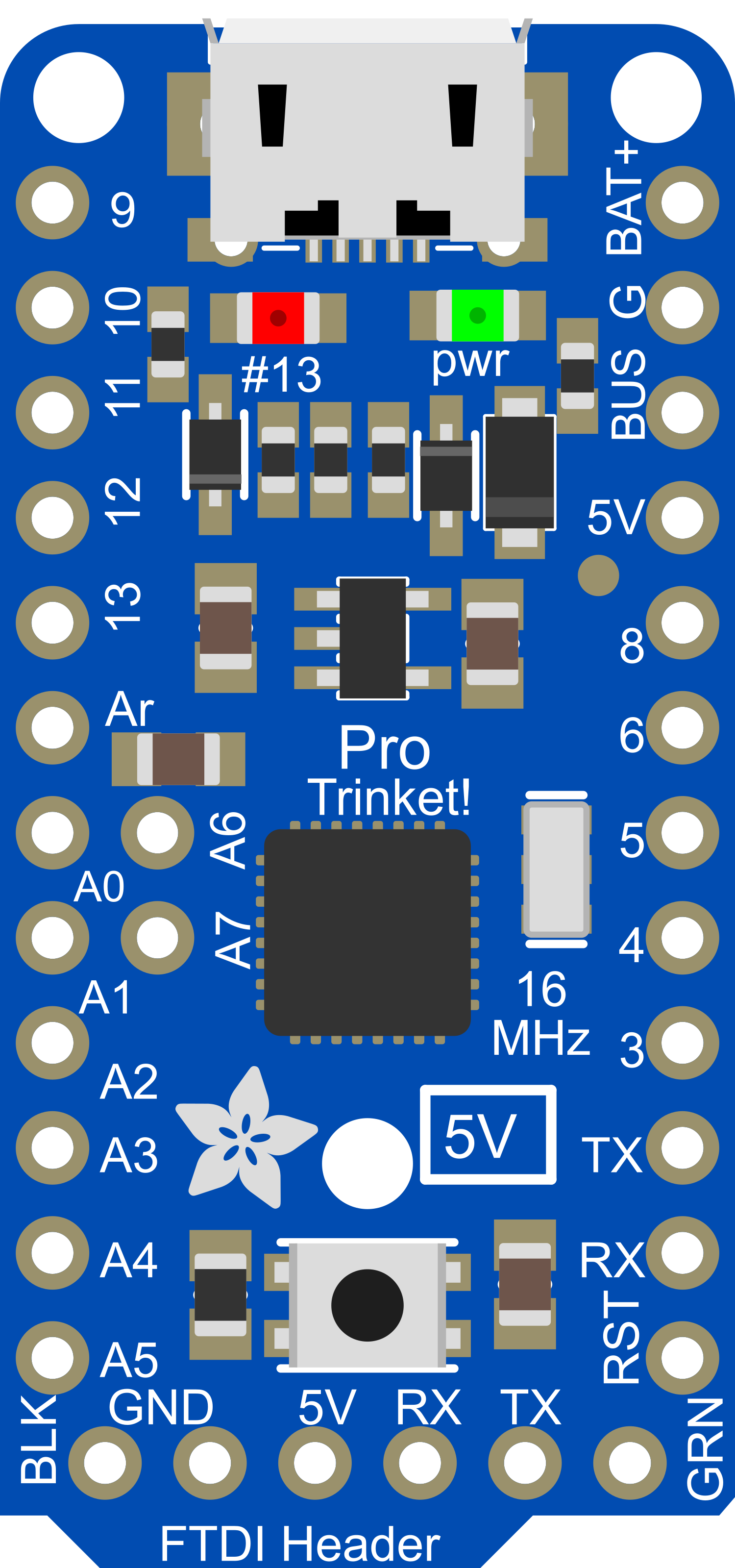
The Adafruit Pro Trinket 5V 16MHz is a compact, Arduino-compatible microcontroller board designed for small projects where space is at a premium. It is based on the ATmega328P microcontroller and operates at a clock speed of 16MHz. The board is compatible with 5V logic levels and can be powered through a USB connection or an external power supply. With 18 digital input/output pins, 2 analog inputs, and support for SPI, I2C, and UART communication protocols, the Pro Trinket is versatile for a wide range of applications, from wearables to sensor networks.

Explore Projects Built with Adafruit Pro Trinket 5V 16MHz

Use Cirkit Designer to design, explore, and prototype these projects online. Some projects support real-time simulation. Click "Open Project" to start designing instantly!
Battery-Powered Smart Sensor Hub with Adafruit QT Py RP2040
Image of wearable final: A project utilizing Adafruit Pro Trinket 5V 16MHz in a practical application
This circuit features an Adafruit QT Py RP2040 microcontroller interfaced with an APDS9960 proximity sensor, an MPU6050 accelerometer and gyroscope, and an OLED display via I2C communication. It also includes a buzzer controlled by the microcontroller and is powered by a 3.7V LiPo battery with a toggle switch for power control.
Cirkit Designer LogoOpen Project in Cirkit Designer
ATmega328P-Based Sensor Hub with OLED Display and LIDAR
Image of TILTPCB: A project utilizing Adafruit Pro Trinket 5V 16MHz in a practical application
This circuit features an Mtiny Uno ATmega328P microcontroller as its central processing unit, interfacing with a variety of sensors and peripherals. It includes a 0.96" OLED display and an MPU6050 accelerometer/gyroscope for user interface and motion sensing, respectively. The circuit also integrates a TF LUNA LIDAR for distance measurement, a DHT11 sensor for temperature and humidity readings, and uses a 9V battery with a 7805 voltage regulator for power management. Communication with a computer for programming and data exchange is facilitated by an Adafruit FTDI Friend module.
Cirkit Designer LogoOpen Project in Cirkit Designer
Battery-Powered Gas Sensor and Servo Control with Adafruit Trinket M0
Image of Canary: A project utilizing Adafruit Pro Trinket 5V 16MHz in a practical application
This circuit is a sensor-based system that uses an Adafruit Trinket M0 microcontroller to read data from a MiCS-5524 gas sensor and control a Tower Pro SG90 servo motor. Additionally, it includes an Adafruit Audio FX Mini Sound Board connected to a STEMMA speaker for audio output, all powered by a 4xAA battery pack.
Cirkit Designer LogoOpen Project in Cirkit Designer
Battery-Powered Smart Light with Proximity Sensor and OLED Display using Adafruit QT Py RP2040
Image of lab: A project utilizing Adafruit Pro Trinket 5V 16MHz in a practical application
This circuit is a portable, battery-powered system featuring an Adafruit QT Py RP2040 microcontroller that interfaces with an OLED display, a proximity sensor, an accelerometer, and an RGB LED strip. The system is powered by a lithium-ion battery with a step-up boost converter to provide 5V for the LED strip, and it includes a toggle switch for power control. The microcontroller communicates with the sensors and display via I2C.
Cirkit Designer LogoOpen Project in Cirkit Designer

Explore Projects Built with Adafruit Pro Trinket 5V 16MHz

Use Cirkit Designer to design, explore, and prototype these projects online. Some projects support real-time simulation. Click "Open Project" to start designing instantly!
Image of wearable final: A project utilizing Adafruit Pro Trinket 5V 16MHz in a practical application
Battery-Powered Smart Sensor Hub with Adafruit QT Py RP2040
This circuit features an Adafruit QT Py RP2040 microcontroller interfaced with an APDS9960 proximity sensor, an MPU6050 accelerometer and gyroscope, and an OLED display via I2C communication. It also includes a buzzer controlled by the microcontroller and is powered by a 3.7V LiPo battery with a toggle switch for power control.
Cirkit Designer LogoOpen Project in Cirkit Designer
Image of TILTPCB: A project utilizing Adafruit Pro Trinket 5V 16MHz in a practical application
ATmega328P-Based Sensor Hub with OLED Display and LIDAR
This circuit features an Mtiny Uno ATmega328P microcontroller as its central processing unit, interfacing with a variety of sensors and peripherals. It includes a 0.96" OLED display and an MPU6050 accelerometer/gyroscope for user interface and motion sensing, respectively. The circuit also integrates a TF LUNA LIDAR for distance measurement, a DHT11 sensor for temperature and humidity readings, and uses a 9V battery with a 7805 voltage regulator for power management. Communication with a computer for programming and data exchange is facilitated by an Adafruit FTDI Friend module.
Cirkit Designer LogoOpen Project in Cirkit Designer
Image of Canary: A project utilizing Adafruit Pro Trinket 5V 16MHz in a practical application
Battery-Powered Gas Sensor and Servo Control with Adafruit Trinket M0
This circuit is a sensor-based system that uses an Adafruit Trinket M0 microcontroller to read data from a MiCS-5524 gas sensor and control a Tower Pro SG90 servo motor. Additionally, it includes an Adafruit Audio FX Mini Sound Board connected to a STEMMA speaker for audio output, all powered by a 4xAA battery pack.
Cirkit Designer LogoOpen Project in Cirkit Designer
Image of lab: A project utilizing Adafruit Pro Trinket 5V 16MHz in a practical application
Battery-Powered Smart Light with Proximity Sensor and OLED Display using Adafruit QT Py RP2040
This circuit is a portable, battery-powered system featuring an Adafruit QT Py RP2040 microcontroller that interfaces with an OLED display, a proximity sensor, an accelerometer, and an RGB LED strip. The system is powered by a lithium-ion battery with a step-up boost converter to provide 5V for the LED strip, and it includes a toggle switch for power control. The microcontroller communicates with the sensors and display via I2C.
Cirkit Designer LogoOpen Project in Cirkit Designer

Common Applications and Use Cases

  • Wearable electronics
  • Prototyping IoT devices
  • Small robotics projects
  • USB peripheral development
  • Educational purposes and DIY projects

Technical Specifications

Key Technical Details

  • Microcontroller: ATmega328P
  • Operating Voltage: 5V
  • Clock Speed: 16MHz
  • Digital I/O Pins: 18 (of which 6 provide PWM output)
  • Analog Input Pins: 2
  • Flash Memory: 32 KB (ATmega328P) of which 2 KB used by bootloader
  • SRAM: 2 KB (ATmega328P)
  • EEPROM: 1 KB (ATmega328P)
  • Communication: SPI, I2C, UART
  • USB Connection: Micro-USB for programming and power
  • External Power Supply: 5V to 16V DC

Pin Configuration and Descriptions

Pin Number Function Description
1 GND Ground
2 VBAT Battery +, 3.5-16V DC for battery-powered operation
3 BUS USB +5V to any point in the circuit
4-9 Digital I/O Digital pins D0-D5
10-15 Digital I/O Digital pins D6-D11
16-17 Analog Input Analog pins A0-A1
18 RESET Reset pin
19 3V 3.3V output (150mA max)
20 5V Regulated 5V output (150mA max)

Usage Instructions

How to Use the Component in a Circuit

  1. Powering the Pro Trinket:

    • Connect the Pro Trinket to a computer via a Micro-USB cable to power it and program it.
    • Alternatively, apply an external power supply (5V to 16V DC) to the VBAT pin for battery-powered operation.
  2. Programming the Pro Trinket:

    • Install the Adafruit Pro Trinket board definitions in the Arduino IDE.
    • Select the correct board and port from the Tools menu.
    • Write your sketch and upload it to the Pro Trinket using the Arduino IDE.
  3. Connecting Peripherals:

    • Use the digital and analog pins to connect sensors, actuators, and other components.
    • Ensure that the connected peripherals are compatible with the 5V logic levels.

Important Considerations and Best Practices

  • Always disconnect the Pro Trinket from power sources before making or altering connections.
  • Observe proper polarity when connecting power to avoid damaging the board.
  • Do not exceed the maximum current rating of 150mA for the 3.3V and 5V outputs.
  • Use a current-limiting resistor when connecting LEDs to digital I/O pins.
  • Avoid exposing the board to static discharge, which can damage the microcontroller.

Troubleshooting and FAQs

Common Issues

  • Pro Trinket not recognized by the computer:

    • Ensure the Micro-USB cable is properly connected and is a data cable, not just a charging cable.
    • Check that the correct drivers are installed on your computer.
  • Sketch not uploading:

    • Verify that the correct board and port are selected in the Arduino IDE.
    • Press the reset button on the Pro Trinket right before uploading the sketch.
  • Peripherals not working as expected:

    • Double-check the wiring and connections.
    • Ensure that the code is correctly written and uploaded to the Pro Trinket.

FAQs

Q: Can I power the Pro Trinket with a battery? A: Yes, you can power it with an external battery connected to the VBAT pin.

Q: Is the Pro Trinket 5V compatible with 3.3V logic sensors? A: The Pro Trinket operates at 5V logic levels, so a logic level converter is recommended when interfacing with 3.3V sensors.

Q: How do I reset the Pro Trinket? A: Press the onboard reset button to reset the Pro Trinket.

Q: Can I use the Arduino IDE to program the Pro Trinket? A: Yes, the Arduino IDE can be used to program the Pro Trinket after installing the appropriate board definitions.

Example Code for Arduino UNO

// Blink an LED connected to pin 13 of the Pro Trinket

void setup() {
  pinMode(13, OUTPUT); // Initialize pin 13 as an output
}

void loop() {
  digitalWrite(13, HIGH); // Turn the LED on
  delay(1000);            // Wait for a second
  digitalWrite(13, LOW);  // Turn the LED off
  delay(1000);            // Wait for a second
}

Remember to comment your code adequately for clarity and maintainability. The above example is a simple blink sketch that demonstrates how to control a digital output on the Pro Trinket.