Cirkit Designer Logo
Cirkit Designer
Your all-in-one circuit design IDE
Home / 
Component Documentation

How to Use buck converter: Examples, Pinouts, and Specs

Image of buck converter
Cirkit Designer LogoDesign with buck converter in Cirkit Designer

Introduction

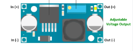
The LM2596 DC-DC Buck Converter is a highly efficient, step-down voltage regulator that is capable of driving a 3A load with excellent line and load regulation. This switch-mode power supply is designed to convert a higher DC voltage to a lower DC voltage with a minimal loss of power. Common applications include on-board power supplies for battery-powered devices, laptop computers, and adjustable power supplies.

Explore Projects Built with buck converter

Use Cirkit Designer to design, explore, and prototype these projects online. Some projects support real-time simulation. Click "Open Project" to start designing instantly!
Multi-Stage Voltage Regulation and Indicator LED Circuit
Image of Subramanyak_Power_Circuit: A project utilizing buck converter in a practical application
This circuit is designed for power management, featuring buck and boost converters for voltage adjustment, and linear regulators for stable voltage output. It includes LEDs for status indication, and terminal blocks for external connections.
Cirkit Designer LogoOpen Project in Cirkit Designer
Dual Motor Control Circuit with Directional Switching and Voltage Regulation
Image of Pencuci Kipas: A project utilizing buck converter in a practical application
This circuit features a 12V battery connected through a rocker switch to two buck converters, one of which steps down the voltage to power two DC mini metal gear motors, and the other is connected to a directional switch that controls a third DC mini metal gear motor. The XL4015 5A DC Buck Step-down converter's output is connected to two motors, allowing them to run at a reduced voltage, while the other buck converter's output is routed through a directional switch to control the direction of the third motor.
Cirkit Designer LogoOpen Project in Cirkit Designer
Battery-Powered DC Generator with XL4015 Buck Converter
Image of conveyor: A project utilizing buck converter in a practical application
This circuit consists of a 12V battery connected to a rocker switch, which controls the input to an XL4015 DC Buck Step-down converter. The converter steps down the voltage to power a DC generator, with the generator's output connected back to the converter to form a feedback loop.
Cirkit Designer LogoOpen Project in Cirkit Designer
Battery-Powered UPS with Step-Down Buck Converter and BMS
Image of Mini ups: A project utilizing buck converter in a practical application
This circuit is a power management system that steps down a 240V AC input to a lower DC voltage using a buck converter, which then powers a 40W UPS. The UPS is controlled by a rocker switch and is backed up by a battery management system (BMS) connected to three 3.7V batteries in series, ensuring continuous power supply.
Cirkit Designer LogoOpen Project in Cirkit Designer

Explore Projects Built with buck converter

Use Cirkit Designer to design, explore, and prototype these projects online. Some projects support real-time simulation. Click "Open Project" to start designing instantly!
Image of Subramanyak_Power_Circuit: A project utilizing buck converter in a practical application
Multi-Stage Voltage Regulation and Indicator LED Circuit
This circuit is designed for power management, featuring buck and boost converters for voltage adjustment, and linear regulators for stable voltage output. It includes LEDs for status indication, and terminal blocks for external connections.
Cirkit Designer LogoOpen Project in Cirkit Designer
Image of Pencuci Kipas: A project utilizing buck converter in a practical application
Dual Motor Control Circuit with Directional Switching and Voltage Regulation
This circuit features a 12V battery connected through a rocker switch to two buck converters, one of which steps down the voltage to power two DC mini metal gear motors, and the other is connected to a directional switch that controls a third DC mini metal gear motor. The XL4015 5A DC Buck Step-down converter's output is connected to two motors, allowing them to run at a reduced voltage, while the other buck converter's output is routed through a directional switch to control the direction of the third motor.
Cirkit Designer LogoOpen Project in Cirkit Designer
Image of conveyor: A project utilizing buck converter in a practical application
Battery-Powered DC Generator with XL4015 Buck Converter
This circuit consists of a 12V battery connected to a rocker switch, which controls the input to an XL4015 DC Buck Step-down converter. The converter steps down the voltage to power a DC generator, with the generator's output connected back to the converter to form a feedback loop.
Cirkit Designer LogoOpen Project in Cirkit Designer
Image of Mini ups: A project utilizing buck converter in a practical application
Battery-Powered UPS with Step-Down Buck Converter and BMS
This circuit is a power management system that steps down a 240V AC input to a lower DC voltage using a buck converter, which then powers a 40W UPS. The UPS is controlled by a rocker switch and is backed up by a battery management system (BMS) connected to three 3.7V batteries in series, ensuring continuous power supply.
Cirkit Designer LogoOpen Project in Cirkit Designer

Technical Specifications

Key Technical Details

  • Output Voltage Range: 1.23V to 37V
  • Input Voltage Range: 4.5V to 40V
  • Output Current: 3A (maximum)
  • Switching Frequency: 150 kHz
  • Efficiency: Up to 92%
  • Operating Temperature Range: -40°C to +125°C

Pin Configuration and Descriptions

Pin Number Name Description
1 Vin Input voltage (4.5V to 40V)
2 Output Regulated output voltage (1.23V to 37V)
3 Ground Common ground for input and output
4 Feedback (FB) Feedback pin for output voltage regulation
5 On/Off Shutdown input: Low = shutdown, High = active

Usage Instructions

How to Use the LM2596 in a Circuit

  1. Input Capacitor: Connect a suitable electrolytic capacitor (typically 100 µF) at the input to reduce the effect of input voltage ripple.
  2. Output Capacitor: Place an electrolytic capacitor (typically 220 µF) at the output to maintain stability and reduce output voltage ripple.
  3. Feedback Resistor Network: Use a pair of resistors to set the output voltage. The formula for calculating the output voltage is: Vout = 1.23V * (1 + R2/R1), where R1 is connected between the output and FB pin, and R2 is connected between FB pin and ground.
  4. Inductor: Choose an inductor that can handle the peak current without saturation. A value around 33 µH is commonly used.
  5. Diode: A Schottky diode with a low forward voltage drop and a current rating higher than the maximum load current should be connected between the output pin and ground.

Important Considerations and Best Practices

  • Ensure that the input voltage is always higher than the desired output voltage.
  • Do not exceed the maximum input voltage of 40V to prevent damage.
  • The maximum output current should not exceed 3A to maintain thermal performance.
  • Use heat sinks if operating at high loads or in high-temperature environments.
  • Keep the feedback path as short as possible to prevent noise interference.

Troubleshooting and FAQs

Common Issues

  • Output Voltage Too High or Low: Check the feedback resistor values and ensure they are correctly calculated and placed.
  • Excessive Output Ripple: Increase the value of the output capacitor or check for a faulty inductor.
  • Thermal Shutdown: Ensure adequate cooling and that the load does not exceed the maximum current rating.

Solutions and Tips

  • If the converter is not starting, check the On/Off pin to ensure it is not being pulled low.
  • Use ceramic capacitors in parallel with electrolytic capacitors for improved high-frequency filtering.
  • Always verify the polarity of the input and output connections to prevent reverse voltage damage.

FAQs

Q: Can I use the LM2596 without an external heat sink? A: Yes, for low power applications or when the ambient temperature is low. However, for continuous operation near the 3A limit, a heat sink is recommended.

Q: How do I adjust the output voltage? A: Adjust the output voltage by changing the values of the feedback resistors R1 and R2 according to the formula provided.

Q: What is the purpose of the On/Off pin? A: The On/Off pin allows you to shut down the regulator, reducing the quiescent current to a minimum when not in use.

Example Code for Arduino UNO

// This example demonstrates how to control the LM2596 using an Arduino UNO
// by toggling the On/Off pin.

const int onOffPin = 7; // Connect this pin to the On/Off pin of LM2596

void setup() {
  pinMode(onOffPin, OUTPUT);
  digitalWrite(onOffPin, HIGH); // Turn on the LM2596
}

void loop() {
  // Toggle the LM2596 On/Off pin every 5 seconds
  digitalWrite(onOffPin, LOW);  // Turn off the LM2596
  delay(5000);
  digitalWrite(onOffPin, HIGH); // Turn on the LM2596
  delay(5000);
}

Note: The above code is for demonstration purposes only. The LM2596 is not a digitally controlled buck converter, and the On/Off pin is typically used for simple enable/disable functionality.