
How to Use Linear Hall Effect Sensor: Examples, Pinouts, and Specs
 Design with Linear Hall Effect Sensor in Cirkit Designer
Introduction
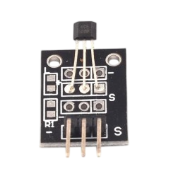
The SS49E Linear Hall Effect Sensor is a versatile device designed to detect the presence and strength of a magnetic field. It provides an analog output voltage that is directly proportional to the magnetic field strength, making it ideal for applications requiring precise magnetic field measurements. This sensor is commonly used in position sensing, current measurement, speed detection, and proximity sensing applications.
Explore Projects Built with Linear Hall Effect Sensor
 Open Project in Cirkit Designer
 Open Project in Cirkit Designer
 Open Project in Cirkit Designer
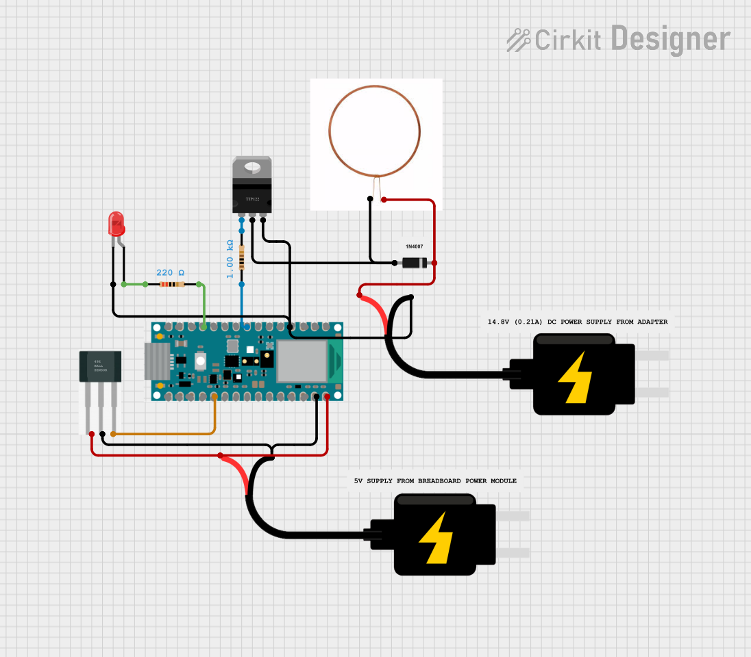 Open Project in Cirkit Designer
Explore Projects Built with Linear Hall Effect Sensor
Open Project in Cirkit DesignerOpen Project in Cirkit DesignerOpen Project in Cirkit DesignerOpen Project in Cirkit DesignerCommon Applications
- Position Sensing: Detecting the position of a magnet in linear or rotary motion systems.
- Current Measurement: Measuring current in circuits by detecting the magnetic field generated by the current flow.
- Proximity Detection: Identifying the presence of magnetic objects.
- Speed Sensing: Monitoring the speed of rotating machinery or wheels.
Technical Specifications
The SS49E is a compact and efficient Hall effect sensor with the following key specifications:
| Parameter | Value |
|---|---|
| Supply Voltage (Vcc) | 4.5V to 6V |
| Output Voltage Range | 0.2V to 4.8V (typical) |
| Sensitivity | 1.4 mV/Gauss (typical) |
| Magnetic Field Range | ±1000 Gauss |
| Operating Temperature | -40°C to +85°C |
| Output Type | Analog |
| Package Type | TO-92 or SOT-23 |
Pin Configuration
The SS49E has three pins, as detailed in the table below:
| Pin Number | Pin Name | Description |
|---|---|---|
| 1 | Vcc | Power supply input (4.5V to 6V) |
| 2 | GND | Ground connection |
| 3 | Vout | Analog output voltage proportional to the magnetic field |
Usage Instructions
How to Use the SS49E in a Circuit
- Power Supply: Connect the Vcc pin to a stable 5V power supply and the GND pin to the ground of the circuit.
- Output Connection: Connect the Vout pin to an analog input pin of a microcontroller or an ADC (Analog-to-Digital Converter) to read the sensor's output voltage.
- Magnetic Field Measurement: Place a magnet near the sensor. The output voltage will vary depending on the strength and polarity of the magnetic field:
- A positive magnetic field (North pole) increases the output voltage.
- A negative magnetic field (South pole) decreases the output voltage.
Important Considerations
- Magnetic Field Range: Ensure the magnetic field strength is within the sensor's range (±1000 Gauss) to avoid saturation.
- Noise Filtering: Use a decoupling capacitor (e.g., 0.1 µF) between Vcc and GND to reduce noise.
- Placement: Avoid placing the sensor near strong electromagnetic interference (EMI) sources to maintain accurate readings.
Example: Connecting SS49E to an Arduino UNO
Below is an example of how to connect the SS49E to an Arduino UNO and read the sensor's output:
Circuit Connections
- SS49E Pin 1 (Vcc) → Arduino 5V
- SS49E Pin 2 (GND) → Arduino GND
- SS49E Pin 3 (Vout) → Arduino A0 (Analog Input)
Arduino Code
// SS49E Linear Hall Effect Sensor Example
// Reads the analog output of the SS49E and prints the value to the Serial Monitor

const int sensorPin = A0; // SS49E output connected to Arduino A0

void setup() {
  Serial.begin(9600); // Initialize serial communication at 9600 baud
}

void loop() {
  int sensorValue = analogRead(sensorPin); // Read the analog value from the sensor
  float voltage = sensorValue * (5.0 / 1023.0); // Convert ADC value to voltage

  // Print the sensor value and voltage to the Serial Monitor
  Serial.print("Sensor Value: ");
  Serial.print(sensorValue);
  Serial.print(" | Voltage: ");
  Serial.print(voltage);
  Serial.println(" V");

  delay(500); // Wait for 500ms before the next reading
}
Troubleshooting and FAQs
Common Issues
No Output Voltage:
- Cause: Incorrect wiring or no power supply.
- Solution: Verify the connections and ensure the Vcc pin is connected to a 5V power source.
Fluctuating Output:
- Cause: Electrical noise or unstable power supply.
- Solution: Add a decoupling capacitor (e.g., 0.1 µF) between Vcc and GND.
Output Voltage Stuck at Maximum or Minimum:
- Cause: Magnetic field strength exceeds the sensor's range.
- Solution: Ensure the magnetic field is within the ±1000 Gauss range.
Incorrect Readings:
- Cause: Sensor placed near EMI sources or incorrect ADC configuration.
- Solution: Relocate the sensor away from EMI sources and verify the microcontroller's ADC settings.
FAQs
Q1: Can the SS49E detect non-magnetic materials?
A1: No, the SS49E is designed to detect magnetic fields and cannot sense non-magnetic materials.
Q2: What happens if the supply voltage exceeds 6V?
A2: Exceeding the maximum supply voltage can damage the sensor. Always use a regulated 5V power supply.
Q3: Can I use the SS49E with a 3.3V microcontroller?
A3: The SS49E requires a minimum supply voltage of 4.5V. You can use a level shifter or a separate 5V power supply for the sensor.
Q4: How do I calibrate the sensor?
A4: Calibration involves measuring the sensor's output in a known magnetic field and adjusting your calculations accordingly. This step is optional but improves accuracy in critical applications.