How to Use zx-switch: Examples, Pinouts, and Specs
Introduction
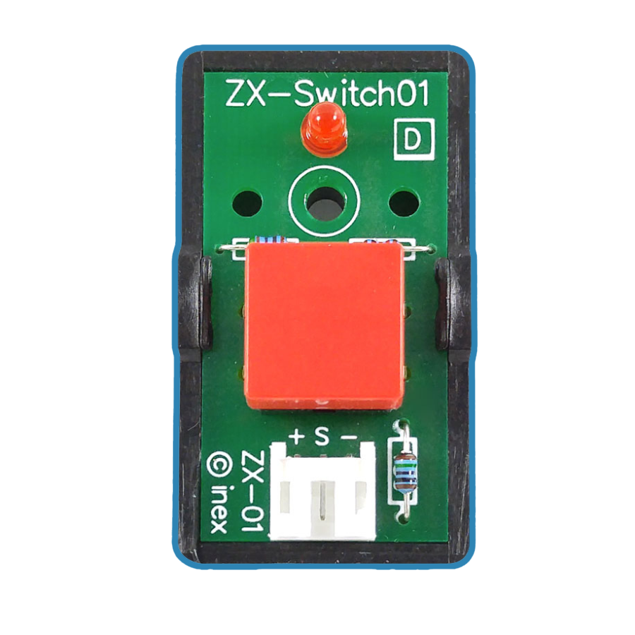
The ZX-Switch, manufactured by INEX, is a versatile electronic switch designed to control the flow of current in a circuit. It can either allow or interrupt current, making it an essential component for power control and signal routing applications. Its compact design and reliable performance make it suitable for a wide range of projects, from simple DIY circuits to complex industrial systems.
Explore Projects Built with zx-switch


Explore Projects Built with zx-switch
Common Applications and Use Cases
- Power control for electronic devices
- Signal routing in communication systems
- Automation and control systems
- DIY electronics and prototyping
- Integration with microcontrollers like Arduino for smart switching
Technical Specifications
The ZX-Switch is designed to operate efficiently in various environments. Below are its key technical details:
| Parameter | Value |
|---|---|
| Operating Voltage | 3.3V to 12V |
| Maximum Current Rating | 2A |
| Switching Speed | < 10ms |
| Contact Resistance | < 50 mΩ |
| Operating Temperature | -20°C to 85°C |
| Dimensions | 10mm x 5mm x 3mm |
Pin Configuration and Descriptions
The ZX-Switch has three pins, as described in the table below:
| Pin | Name | Description |
|---|---|---|
| 1 | Input (IN) | Input terminal for the control signal or voltage. |
| 2 | Output (OUT) | Output terminal where the controlled current flows. |
| 3 | Ground (GND) | Ground connection for the circuit. |
Usage Instructions
The ZX-Switch is straightforward to use in a circuit. Follow the steps below to integrate it effectively:
Connect the Input Pin (IN):
Attach the control signal or voltage source to the IN pin. Ensure the voltage is within the operating range (3.3V to 12V).Connect the Output Pin (OUT):
Connect the device or load you want to control to the OUT pin. Ensure the load does not exceed the maximum current rating of 2A.Connect the Ground Pin (GND):
Connect the GND pin to the ground of your circuit to complete the connection.Power the Circuit:
Once all connections are secure, power the circuit. The ZX-Switch will allow or interrupt current flow based on the control signal applied to the IN pin.
Important Considerations and Best Practices
- Avoid Overloading: Ensure the connected load does not exceed the 2A current rating to prevent damage to the switch.
- Debounce the Input Signal: If using a mechanical switch or button to control the ZX-Switch, consider adding a debounce circuit or software debounce to avoid erratic behavior.
- Heat Dissipation: For high-current applications, ensure proper ventilation or heat dissipation to maintain optimal performance.
- Polarity: Double-check the polarity of the connections to avoid damage to the component.
Example: Using the ZX-Switch with an Arduino UNO
The ZX-Switch can be easily controlled using an Arduino UNO. Below is an example circuit and code to toggle the switch using a digital pin.
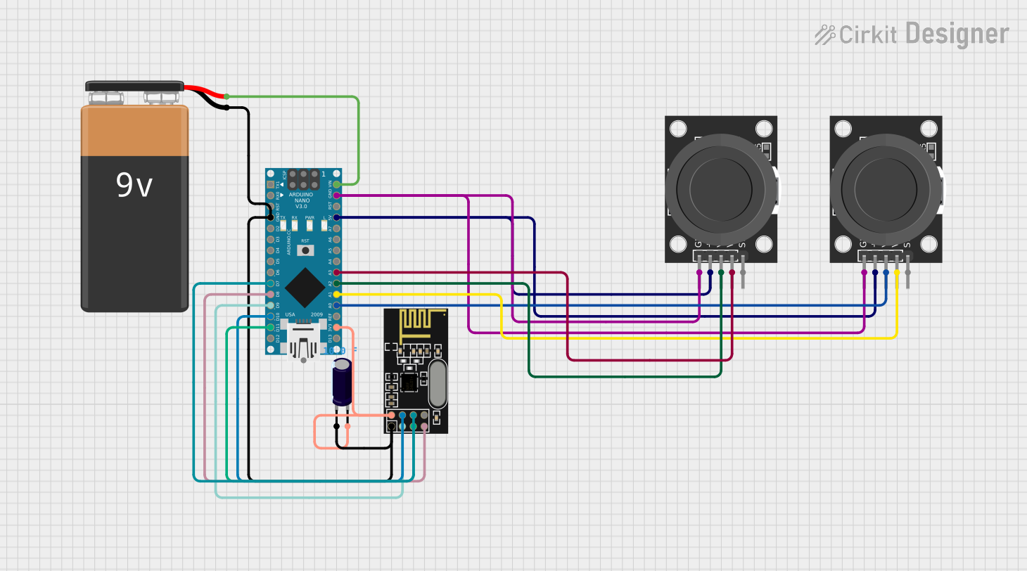
Circuit Diagram
- Connect the IN pin of the ZX-Switch to Arduino digital pin 7.
- Connect the OUT pin to the positive terminal of the load (e.g., an LED with a resistor).
- Connect the GND pin to the Arduino GND.
Arduino Code
// Example code to control the ZX-Switch with an Arduino UNO
// The ZX-Switch is connected to digital pin 7

#define SWITCH_PIN 7  // Define the pin connected to the ZX-Switch

void setup() {
  pinMode(SWITCH_PIN, OUTPUT);  // Set the pin as an output
}

void loop() {
  digitalWrite(SWITCH_PIN, HIGH);  // Turn the switch ON
  delay(1000);                     // Wait for 1 second
  digitalWrite(SWITCH_PIN, LOW);   // Turn the switch OFF
  delay(1000);                     // Wait for 1 second
}
Troubleshooting and FAQs
Common Issues and Solutions
The switch does not respond to the control signal.
- Solution: Verify that the input voltage is within the operating range (3.3V to 12V). Check the connections for loose wires or incorrect polarity.
The load does not turn on or off as expected.
- Solution: Ensure the load does not exceed the maximum current rating of 2A. Check for proper grounding and verify the control signal logic.
The switch overheats during operation.
- Solution: Reduce the load current or improve heat dissipation by adding a heatsink or ensuring proper ventilation.
The switch behaves erratically when controlled by a button.
- Solution: Add a debounce circuit or implement software debounce in your microcontroller code.
FAQs
Q: Can the ZX-Switch handle AC signals?
A: No, the ZX-Switch is designed for DC circuits only. Using it with AC signals may damage the component.
Q: Is the ZX-Switch compatible with 5V logic levels?
A: Yes, the ZX-Switch operates within a voltage range of 3.3V to 12V, making it compatible with 5V logic levels.
Q: Can I use the ZX-Switch to control a motor?
A: Yes, as long as the motor's current draw does not exceed 2A. For higher currents, consider using a relay or MOSFET.
Q: Does the ZX-Switch require an external resistor?
A: No external resistor is required for the switch itself, but you may need a current-limiting resistor for connected components like LEDs.
By following this documentation, you can effectively integrate the ZX-Switch into your projects and troubleshoot any issues that arise.