How to Use aa1: Examples, Pinouts, and Specs
Introduction
The AA1 is an integrated circuit (IC) manufactured by AA, designed for use in a wide range of electronic applications. It is commonly employed as an amplifier or signal processor, making it a versatile component in audio systems, communication devices, and instrumentation circuits. Its compact design and reliable performance make it a popular choice for both hobbyists and professionals.
Explore Projects Built with aa1
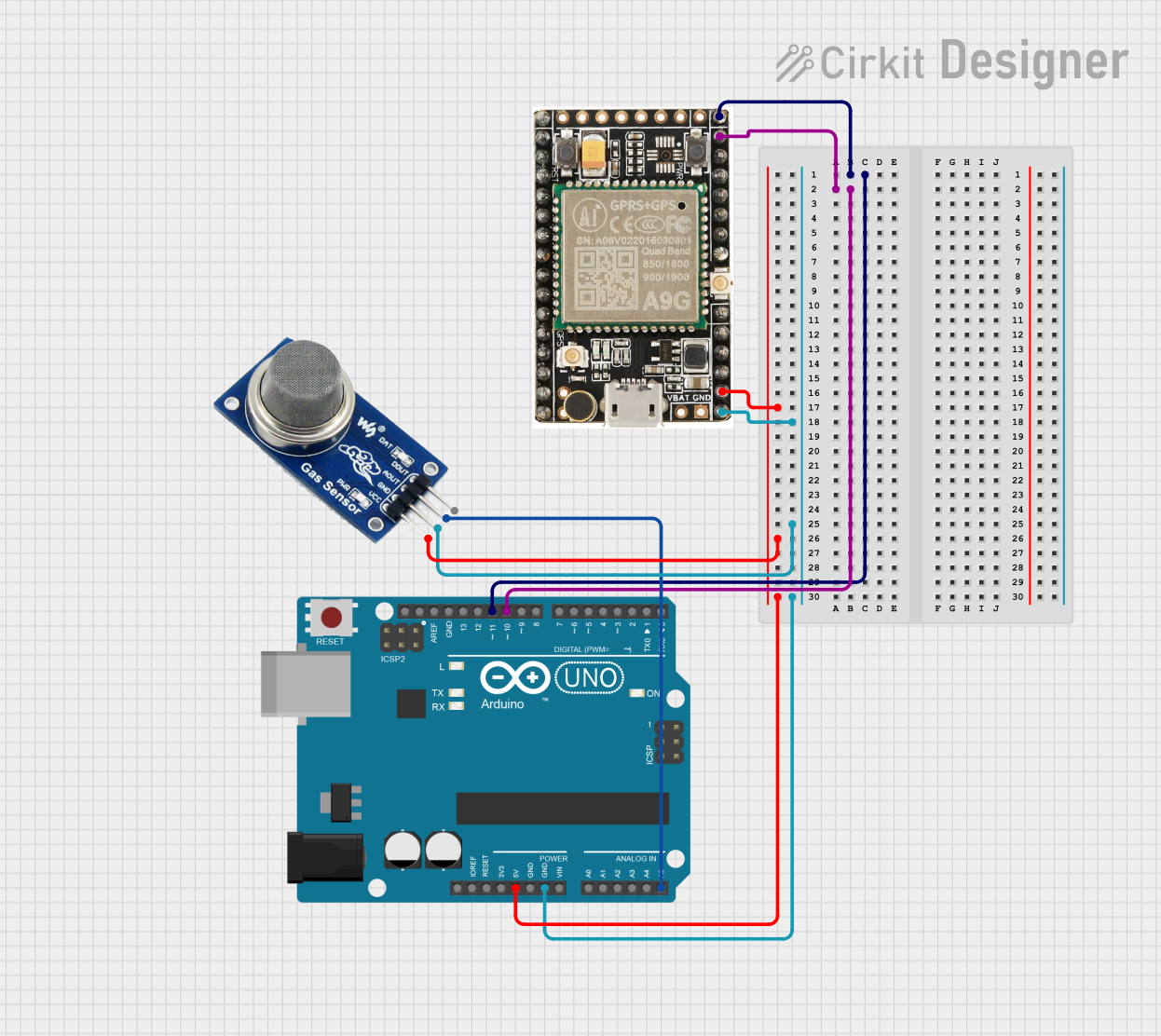
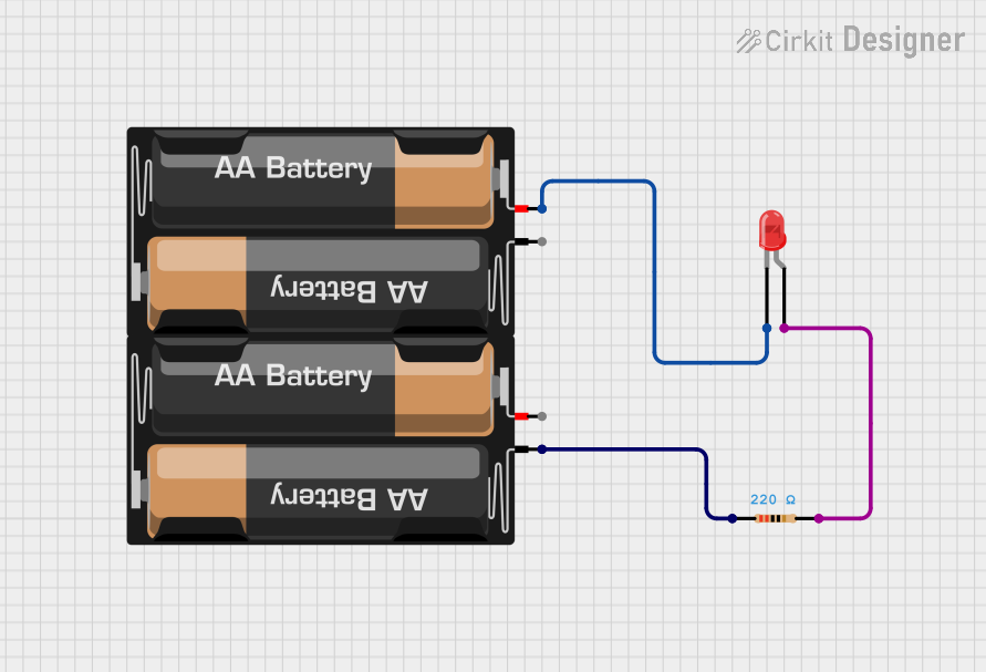
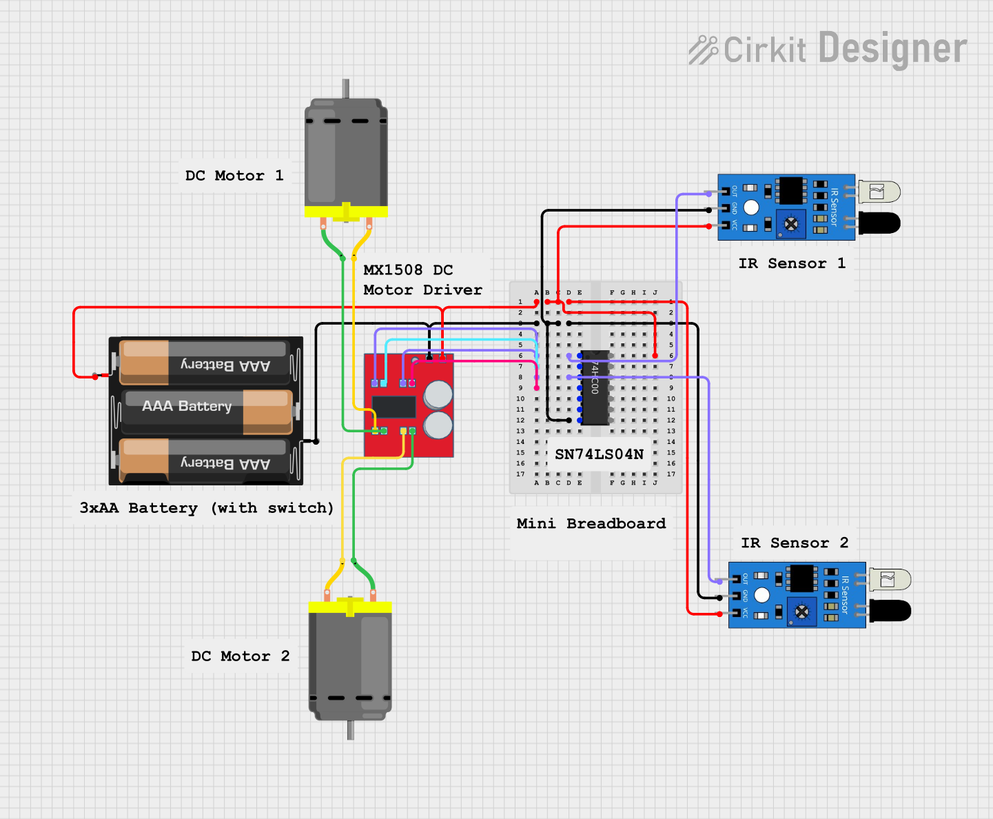
Explore Projects Built with aa1
Common Applications
- Audio signal amplification
- Signal conditioning in communication systems
- Analog signal processing in instrumentation
- General-purpose amplification in electronic circuits
Technical Specifications
The AA1 IC is designed to operate efficiently under a variety of conditions. Below are its key technical specifications:
| Parameter | Value |
|---|---|
| Supply Voltage (Vcc) | 5V to 15V |
| Operating Current | 10mA (typical) |
| Input Voltage Range | 0V to Vcc |
| Output Voltage Range | 0.1V to Vcc - 0.1V |
| Gain | Adjustable (up to 100x) |
| Operating Temperature | -40°C to +85°C |
| Package Type | DIP-8 or SOIC-8 |
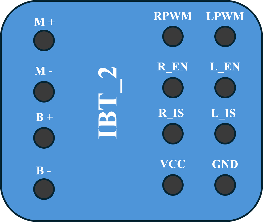
Pin Configuration
The AA1 IC typically comes in an 8-pin Dual Inline Package (DIP-8) or Small Outline Integrated Circuit (SOIC-8). Below is the pinout and description:
| Pin Number | Pin Name | Description |
|---|---|---|
| 1 | IN+ | Non-inverting input |
| 2 | IN- | Inverting input |
| 3 | GND | Ground (0V reference) |
| 4 | Vcc | Positive power supply |
| 5 | OUT | Output signal |
| 6 | NC | No connection (leave unconnected) |
| 7 | GAIN | Gain adjustment (connect resistor/capacitor) |
| 8 | NC | No connection (leave unconnected) |
Usage Instructions
The AA1 IC is straightforward to use in a variety of circuits. Below are the steps and considerations for integrating it into your design:
Basic Amplifier Circuit
- Power Supply: Connect the Vcc pin (Pin 4) to a stable DC power supply (5V to 15V). Connect the GND pin (Pin 3) to the ground of the circuit.
- Input Signal: Feed the input signal to the IN+ (Pin 1) or IN- (Pin 2) pin, depending on whether you need non-inverting or inverting amplification.
- Output Signal: The amplified signal will be available at the OUT pin (Pin 5).
- Gain Adjustment: Connect a resistor or capacitor between the GAIN pin (Pin 7) and ground to set the desired gain. Refer to the datasheet for recommended values.
Important Considerations
- Bypass Capacitor: Place a 0.1µF ceramic capacitor close to the Vcc pin to filter out noise from the power supply.
- Input Impedance: Ensure the input impedance of the circuit matches the source impedance for optimal performance.
- Thermal Management: Operate the IC within the specified temperature range to avoid overheating.
Example: Using AA1 with Arduino UNO
The AA1 can be used with an Arduino UNO to amplify an analog signal. Below is an example circuit and code:
Circuit Connections
- Connect the AA1's Vcc pin to the Arduino's 5V pin.
- Connect the GND pin to the Arduino's GND.
- Feed an analog signal to the IN+ pin.
- Connect the OUT pin to one of the Arduino's analog input pins (e.g., A0).
Arduino Code
// Example code to read amplified signal from AA1 using Arduino UNO
const int analogPin = A0; // Pin connected to AA1 OUT pin
int signalValue = 0;      // Variable to store the analog signal value

void setup() {
  Serial.begin(9600); // Initialize serial communication at 9600 baud
}

void loop() {
  signalValue = analogRead(analogPin); // Read the amplified signal
  Serial.print("Signal Value: ");
  Serial.println(signalValue); // Print the signal value to the Serial Monitor
  delay(500); // Wait for 500ms before the next reading
}
Troubleshooting and FAQs
Common Issues
No Output Signal
- Cause: Incorrect power supply or loose connections.
- Solution: Verify that the Vcc and GND pins are properly connected and the supply voltage is within the specified range.
Distorted Output
- Cause: Gain set too high or input signal exceeds the input voltage range.
- Solution: Reduce the gain by adjusting the resistor/capacitor on the GAIN pin. Ensure the input signal is within the specified range.
Overheating
- Cause: Operating outside the recommended temperature range or excessive current draw.
- Solution: Check the operating conditions and ensure proper thermal management.
FAQs
Q1: Can the AA1 be used for audio amplification?
A1: Yes, the AA1 is well-suited for audio signal amplification due to its adjustable gain and low noise characteristics.
Q2: What is the maximum gain of the AA1?
A2: The gain can be adjusted up to 100x, depending on the external components connected to the GAIN pin.
Q3: Can I use the AA1 with a 3.3V power supply?
A3: No, the minimum supply voltage for the AA1 is 5V. Using a lower voltage may result in improper operation.
Q4: What should I do if the output signal is noisy?
A4: Add a bypass capacitor (0.1µF) near the Vcc pin and ensure proper grounding to minimize noise.
By following this documentation, you can effectively integrate the AA1 IC into your projects and troubleshoot common issues with ease.