How to Use NANO 5A SUMO CONTROLLER: Examples, Pinouts, and Specs
Introduction
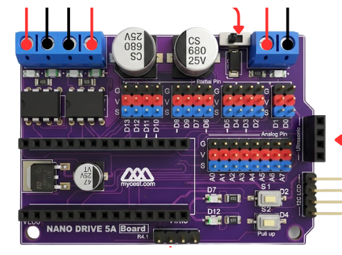
The NANO 5A SUMO CONTROLLER by MYCEST (Part ID: NANO 5A) is a compact and efficient motor controller specifically designed for managing the movement and operations of sumo robots. With a 5A current rating, it is capable of handling high-power motors, making it ideal for competitive robotics applications. Its small form factor and robust design ensure reliable performance in demanding environments.
Explore Projects Built with NANO 5A SUMO CONTROLLER

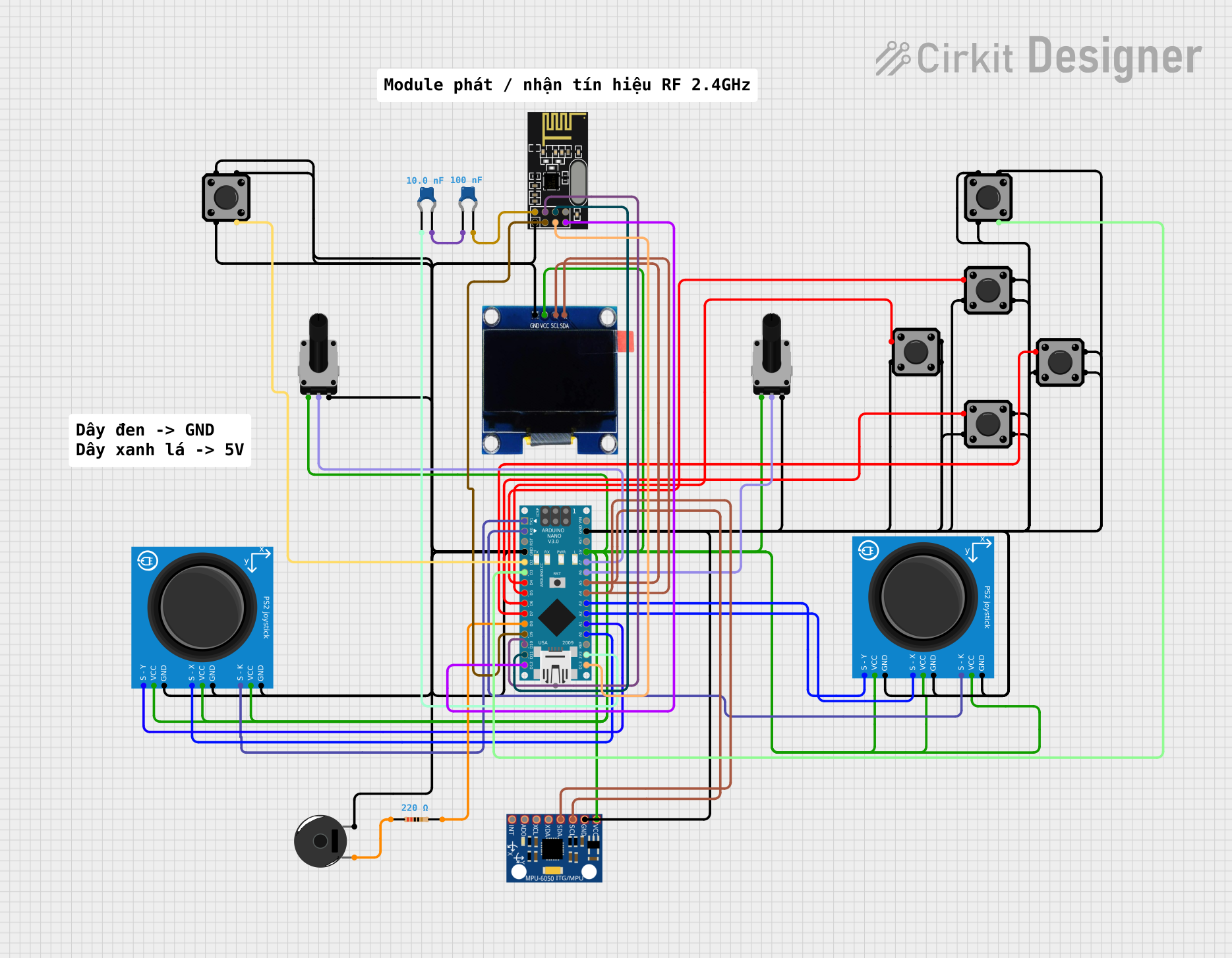
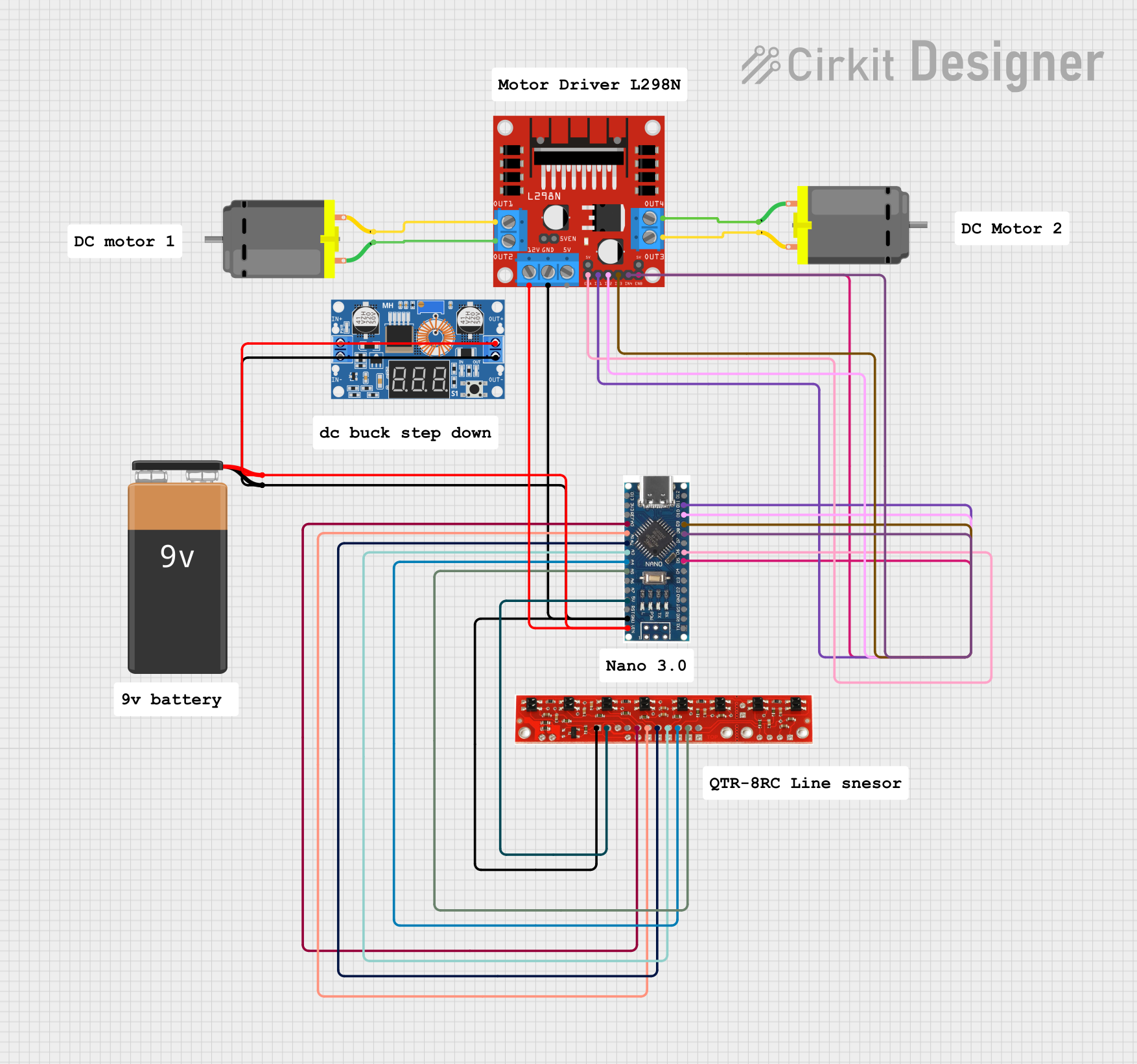
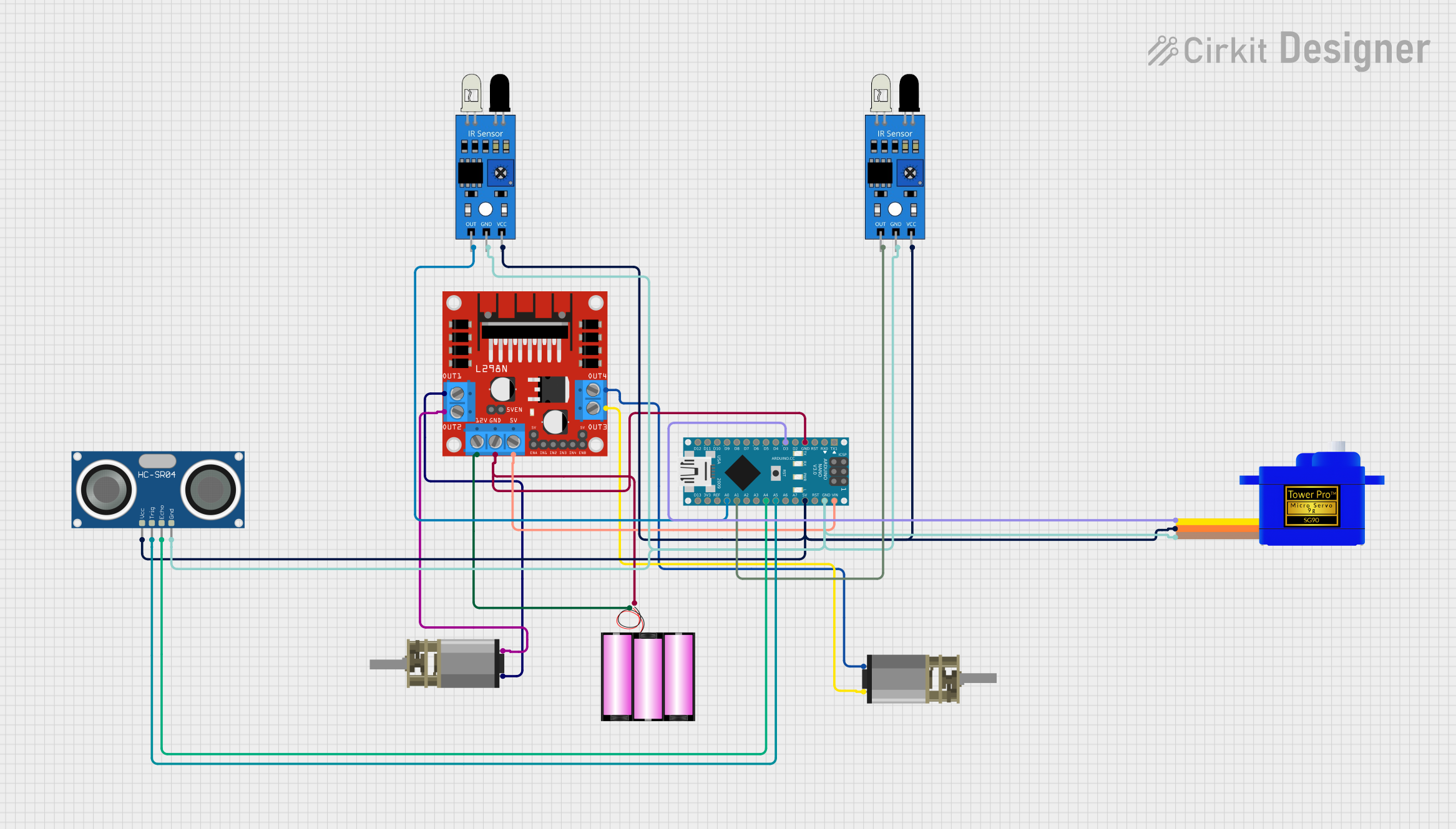
Explore Projects Built with NANO 5A SUMO CONTROLLER
Common Applications and Use Cases
- Sumo robots for competitive robotics
- Small to medium-sized robotic platforms
- High-torque motor control for hobbyist and educational projects
- Projects requiring precise motor speed and direction control
Technical Specifications
The following table outlines the key technical details of the NANO 5A SUMO CONTROLLER:
| Parameter | Specification |
|---|---|
| Operating Voltage | 6V to 24V DC |
| Continuous Current | 5A |
| Peak Current | 10A (for short durations) |
| Motor Channels | 2 (independent control) |
| Control Interface | PWM and Direction (DIR) pins |
| Logic Voltage | 3.3V or 5V compatible |
| Dimensions | 40mm x 30mm x 10mm |
| Weight | 15g |
| Protection Features | Overcurrent, Overtemperature, Reverse Polarity |
Pin Configuration and Descriptions
The NANO 5A SUMO CONTROLLER has a simple pinout for easy integration into your projects. The pin configuration is as follows:
| Pin Name | Type | Description |
|---|---|---|
| VIN | Power Input | Connect to the motor power supply (6V to 24V DC). |
| GND | Power Ground | Ground connection for the power supply and logic. |
| M1+ | Motor Output | Positive terminal for Motor 1. |
| M1- | Motor Output | Negative terminal for Motor 1. |
| M2+ | Motor Output | Positive terminal for Motor 2. |
| M2- | Motor Output | Negative terminal for Motor 2. |
| PWM1 | Logic Input | PWM signal input for Motor 1 speed control. |
| DIR1 | Logic Input | Direction control input for Motor 1. |
| PWM2 | Logic Input | PWM signal input for Motor 2 speed control. |
| DIR2 | Logic Input | Direction control input for Motor 2. |
| EN | Logic Input | Enable pin. Pull HIGH to enable the controller, LOW to disable. |
| 5V | Logic Power | Optional 5V output for powering external logic circuits (max 100mA). |
Usage Instructions
How to Use the Component in a Circuit
- Power Supply: Connect a DC power supply (6V to 24V) to the VIN and GND pins. Ensure the power supply can provide sufficient current for your motors.
- Motor Connections: Connect the motors to the M1+/M1- and M2+/M2- terminals. Ensure the motors are within the controller's current rating.
- Logic Connections:
- Connect the PWM1 and DIR1 pins to your microcontroller for Motor 1 control.
- Connect the PWM2 and DIR2 pins to your microcontroller for Motor 2 control.
- Use the EN pin to enable or disable the controller.
- Logic Voltage Compatibility: The controller is compatible with both 3.3V and 5V logic levels, making it suitable for most microcontrollers, including Arduino and Raspberry Pi.
Important Considerations and Best Practices
- Heat Dissipation: The controller may heat up during operation. Ensure proper ventilation or use a heatsink if operating near the maximum current rating.
- Current Limits: Avoid exceeding the 5A continuous current rating to prevent damage to the controller.
- Reverse Polarity Protection: While the controller has built-in reverse polarity protection, always double-check your connections to avoid accidental damage.
- PWM Frequency: Use a PWM frequency between 1kHz and 20kHz for optimal motor performance.
Example Code for Arduino UNO
Below is an example code snippet to control two motors using the NANO 5A SUMO CONTROLLER with an Arduino UNO:
// Define motor control pins
const int PWM1 = 3;  // PWM pin for Motor 1
const int DIR1 = 4;  // Direction pin for Motor 1
const int PWM2 = 5;  // PWM pin for Motor 2
const int DIR2 = 6;  // Direction pin for Motor 2
const int EN = 7;    // Enable pin for the controller

void setup() {
  // Set pin modes
  pinMode(PWM1, OUTPUT);
  pinMode(DIR1, OUTPUT);
  pinMode(PWM2, OUTPUT);
  pinMode(DIR2, OUTPUT);
  pinMode(EN, OUTPUT);

  // Enable the motor controller
  digitalWrite(EN, HIGH);
}

void loop() {
  // Example: Move both motors forward at 50% speed
  digitalWrite(DIR1, HIGH);  // Set Motor 1 direction forward
  analogWrite(PWM1, 128);    // Set Motor 1 speed (128/255 = 50%)

  digitalWrite(DIR2, HIGH);  // Set Motor 2 direction forward
  analogWrite(PWM2, 128);    // Set Motor 2 speed (128/255 = 50%)

  delay(2000);  // Run for 2 seconds

  // Example: Reverse both motors at 75% speed
  digitalWrite(DIR1, LOW);   // Set Motor 1 direction reverse
  analogWrite(PWM1, 192);    // Set Motor 1 speed (192/255 = 75%)

  digitalWrite(DIR2, LOW);   // Set Motor 2 direction reverse
  analogWrite(PWM2, 192);    // Set Motor 2 speed (192/255 = 75%)

  delay(2000);  // Run for 2 seconds
}
Troubleshooting and FAQs
Common Issues and Solutions
Motors Not Running:
- Ensure the EN pin is pulled HIGH to enable the controller.
- Verify the power supply voltage and current are sufficient for the motors.
- Check the PWM and DIR signals from the microcontroller.
Overheating:
- Ensure the controller is not exceeding the 5A continuous current rating.
- Provide adequate ventilation or use a heatsink.
Erratic Motor Behavior:
- Verify the PWM frequency is within the recommended range (1kHz to 20kHz).
- Check for loose or faulty connections.
Controller Not Responding:
- Ensure the logic voltage levels (3.3V or 5V) are correctly matched to the microcontroller.
- Double-check all wiring and connections.
FAQs
Q: Can I use the NANO 5A SUMO CONTROLLER with a 12V battery?
A: Yes, the controller supports a wide operating voltage range of 6V to 24V, so a 12V battery is suitable.
Q: What happens if I exceed the 5A current rating?
A: The controller has built-in overcurrent protection, but exceeding the rating frequently may cause overheating or damage. Always use motors within the specified limits.
Q: Can I control only one motor with this controller?
A: Yes, you can use just one motor by connecting it to either Motor 1 or Motor 2 terminals and leaving the other set of terminals unconnected.
Q: Is the controller compatible with Raspberry Pi?
A: Yes, the controller is compatible with 3.3V logic levels, making it suitable for Raspberry Pi and other similar platforms.