How to Use usbc: Examples, Pinouts, and Specs
Introduction
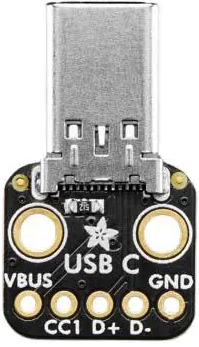
The USB Type-C (Adafruit 5978) is a versatile and universal connector standard designed to support multiple functionalities, including data transfer, video output, and power delivery. This compact and reversible connector is widely adopted in modern electronics due to its ability to handle high-speed data transmission, deliver power up to 100W, and support alternate modes like DisplayPort and HDMI.
Explore Projects Built with usbc


Explore Projects Built with usbc
Common Applications and Use Cases
- Power Delivery (PD): Fast charging for smartphones, laptops, and other devices.
- Data Transfer: High-speed data communication for external drives, peripherals, and more.
- Video Output: Connecting monitors and displays via alternate modes (e.g., DisplayPort).
- Universal Connectivity: Replacing older USB standards for a single, unified interface.
Technical Specifications
The Adafruit 5978 USB Type-C connector is designed for robust performance and ease of integration into various projects. Below are the key technical details:
Key Specifications
| Parameter | Value |
|---|---|
| Connector Type | USB Type-C |
| Manufacturer | Adafruit |
| Part ID | 5978 |
| Voltage Rating | Up to 20V |
| Current Rating | Up to 5A |
| Power Delivery Support | Yes (up to 100W) |
| Data Transfer Speeds | Up to 10 Gbps (USB 3.1 Gen 2) |
| Reversibility | Yes (plug orientation does not matter) |
| Alternate Modes | Supported (e.g., DisplayPort, HDMI) |
| Operating Temperature | -40°C to 85°C |
Pin Configuration and Descriptions
The USB Type-C connector has 24 pins, divided into two symmetrical rows, allowing for reversible plug orientation. Below is a simplified pinout for common use cases:
| Pin Name | Description | Notes |
|---|---|---|
| GND | Ground | Power return path |
| VBUS | Power supply (5V to 20V) | Used for power delivery |
| CC1, CC2 | Configuration Channel | Detects plug orientation and negotiates PD |
| D+, D- | USB 2.0 differential data pair | Legacy USB 2.0 communication |
| TX1+, TX1- | USB 3.1 SuperSpeed differential TX | High-speed data transmission (lane 1) |
| RX1+, RX1- | USB 3.1 SuperSpeed differential RX | High-speed data reception (lane 1) |
| TX2+, TX2- | USB 3.1 SuperSpeed differential TX | High-speed data transmission (lane 2) |
| RX2+, RX2- | USB 3.1 SuperSpeed differential RX | High-speed data reception (lane 2) |
| SBU1, SBU2 | Sideband Use | Used for alternate modes (e.g., audio) |
Usage Instructions
The Adafruit 5978 USB Type-C connector can be integrated into a variety of projects, from simple power delivery circuits to advanced data and video applications. Below are the steps and best practices for using this component:
How to Use the Component in a Circuit
Power Delivery (PD):
- Connect the VBUS pin to the power input of your circuit.
- Use the CC1 and CC2 pins to negotiate the desired voltage and current with the power source.
- Ensure proper grounding by connecting the GND pin to the circuit ground.
Data Transfer:
- For USB 2.0 communication, connect the D+ and D- pins to the corresponding data lines of your microcontroller or USB interface IC.
- For USB 3.1 communication, connect the TX/RX differential pairs to the appropriate high-speed data lines.
Video Output:
- Use the SBU1 and SBU2 pins for alternate mode signaling (e.g., DisplayPort).
- Ensure compatibility with the display device and configure the alternate mode as needed.
Reversibility:
- The USB Type-C connector is reversible, so ensure that both CC1 and CC2 are properly connected to detect plug orientation.
Important Considerations and Best Practices
- Power Delivery Compliance: Use a USB PD controller IC to safely negotiate voltage and current levels.
- Signal Integrity: Keep high-speed data lines (TX/RX) short and properly terminated to minimize signal loss.
- Thermal Management: Ensure adequate cooling for high-power applications to prevent overheating.
- ESD Protection: Add ESD protection diodes to sensitive pins to safeguard against electrostatic discharge.
Example: Connecting to an Arduino UNO
While the Arduino UNO does not natively support USB Type-C, you can use the Adafruit 5978 connector for power delivery or USB 2.0 data transfer. Below is an example of using the USB Type-C connector to power an Arduino UNO:
// Example: Powering Arduino UNO via USB Type-C
// Connect the VBUS pin of the USB Type-C connector to the Arduino's VIN pin.
// Connect the GND pin of the USB Type-C connector to the Arduino's GND pin.

// Note: Ensure the USB Type-C power source provides 5V output.
void setup() {
  // No specific setup required for power delivery
}

void loop() {
  // Your Arduino code here
}
Troubleshooting and FAQs
Common Issues and Solutions
Issue: The USB Type-C connector does not provide power.
- Solution: Check the VBUS and GND connections. Ensure the power source is compatible and properly configured.
Issue: Data transfer is unreliable or slow.
- Solution: Verify the connections for D+, D-, and high-speed data lines (TX/RX). Use shielded cables and minimize line lengths.
Issue: The device does not detect alternate modes (e.g., DisplayPort).
- Solution: Ensure the SBU1 and SBU2 pins are correctly connected and the device supports the desired alternate mode.
Issue: Overheating during high-power applications.
- Solution: Check for proper thermal management and ensure the power source does not exceed the connector's current rating.
FAQs
Q: Can I use the Adafruit 5978 for both power and data simultaneously?
A: Yes, the USB Type-C connector supports simultaneous power delivery and data transfer.Q: Do I need a USB PD controller for power delivery?
A: Yes, a USB PD controller is required to negotiate voltage and current levels for power delivery.Q: Is the Adafruit 5978 compatible with older USB standards?
A: Yes, it supports USB 2.0 and USB 3.1, making it backward compatible with older devices.Q: Can I use the Adafruit 5978 for video output?
A: Yes, but you need to configure the alternate mode (e.g., DisplayPort) and ensure compatibility with the display device.