How to Use RTC : Examples, Pinouts, and Specs
Introduction
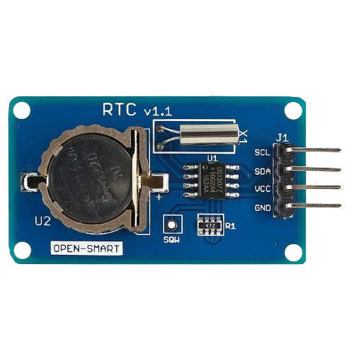
The DS1307 Real-Time Clock (RTC) module, manufactured by Baramee, is a timekeeping device designed to maintain accurate time and date information. It operates independently of the main power supply by utilizing a backup battery, ensuring continuous operation even during power outages. The DS1307 is widely used in applications requiring precise timekeeping, such as data logging, alarms, and scheduling systems.
Explore Projects Built with RTC

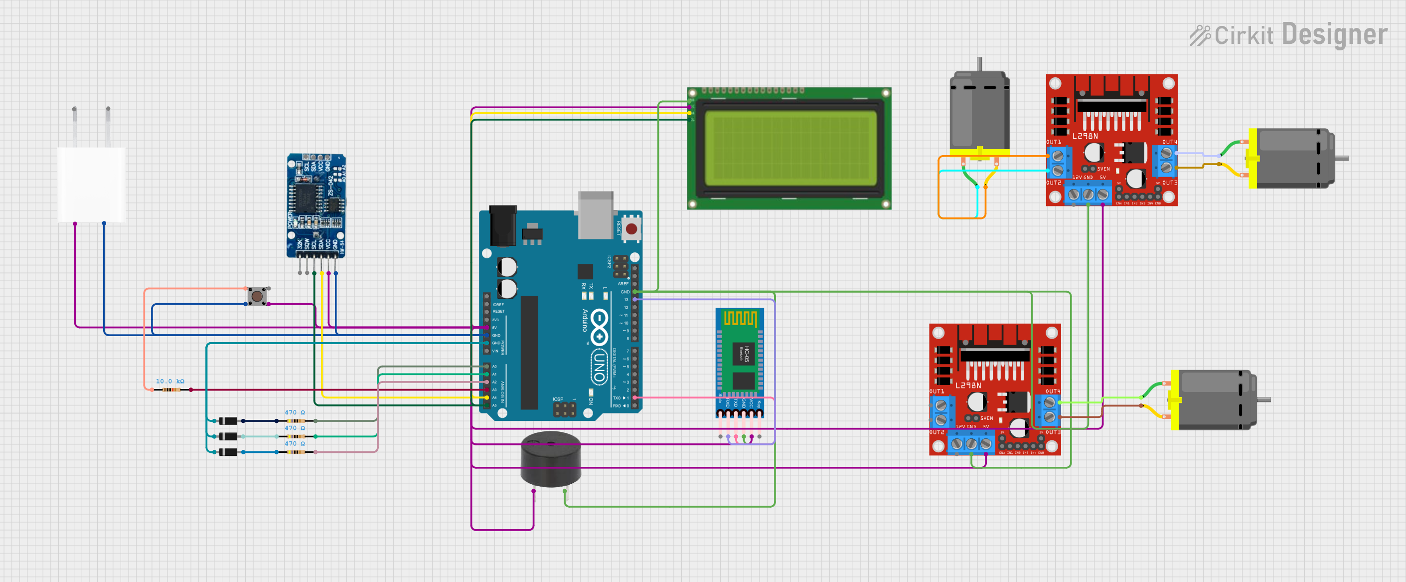
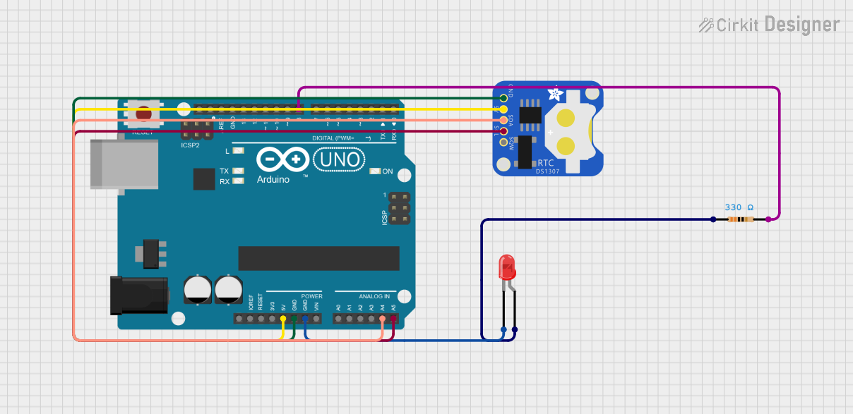
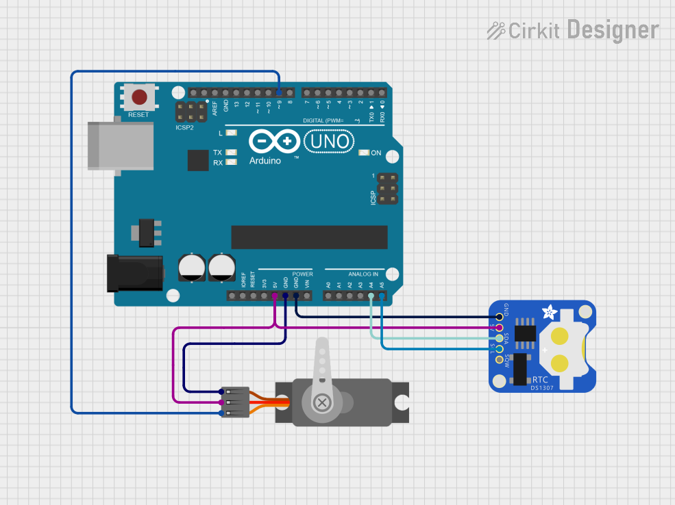
Explore Projects Built with RTC
Common Applications and Use Cases
- Digital clocks and watches
- Data logging systems
- Home automation and IoT devices
- Alarms and timers
- Scheduling systems for industrial and consumer electronics
Technical Specifications
The DS1307 RTC module is a low-power, full binary-coded decimal (BCD) clock/calendar with the following key specifications:
| Parameter | Value |
|---|---|
| Operating Voltage | 4.5V to 5.5V |
| Backup Battery Voltage | 3.0V (typical) |
| Timekeeping Accuracy | ±2 seconds/day (at 25°C) |
| Communication Protocol | I²C (Inter-Integrated Circuit) |
| Clock Format | 12-hour or 24-hour |
| Operating Temperature | -40°C to +85°C |
| Memory | 56 bytes of non-volatile RAM |
| Oscillator Frequency | 32.768 kHz (external crystal required) |
Pin Configuration and Descriptions
The DS1307 RTC module has 8 pins, as described in the table below:
| Pin Number | Pin Name | Description |
|---|---|---|
| 1 | X1 | Oscillator input (connect to 32.768 kHz crystal) |
| 2 | X2 | Oscillator output (connect to 32.768 kHz crystal) |
| 3 | VBAT | Backup battery input (3V coin cell recommended) |
| 4 | GND | Ground |
| 5 | SDA | Serial Data Line for I²C communication |
| 6 | SCL | Serial Clock Line for I²C communication |
| 7 | NC | No connection |
| 8 | VCC | Power supply input (4.5V to 5.5V) |
Usage Instructions
How to Use the DS1307 in a Circuit
- Power Supply: Connect the VCC pin to a 5V power source and the GND pin to ground.
- Backup Battery: Attach a 3V coin cell battery to the VBAT pin to ensure timekeeping during power loss.
- Oscillator: Connect a 32.768 kHz crystal oscillator between the X1 and X2 pins.
- I²C Communication: Connect the SDA and SCL pins to the corresponding I²C pins on your microcontroller (e.g., Arduino UNO).
- Pull-Up Resistors: Use 4.7kΩ pull-up resistors on the SDA and SCL lines for proper I²C operation.
Important Considerations and Best Practices
- Ensure the backup battery is properly installed to maintain timekeeping during power interruptions.
- Use decoupling capacitors (e.g., 0.1µF) near the VCC pin to reduce noise and improve stability.
- Avoid placing the crystal oscillator near high-frequency components to minimize interference.
- Verify the I²C address of the DS1307 (default: 0x68) when using multiple I²C devices.
Example Code for Arduino UNO
Below is an example Arduino sketch to interface with the DS1307 RTC module:
#include <Wire.h>
#include <RTClib.h> // Include the Adafruit RTC library

RTC_DS1307 rtc; // Create an RTC object

void setup() {
  Serial.begin(9600); // Initialize serial communication
  Wire.begin();       // Initialize I²C communication

  if (!rtc.begin()) {
    Serial.println("RTC not found! Check connections.");
    while (1); // Halt execution if RTC is not detected
  }

  if (!rtc.isrunning()) {
    Serial.println("RTC is not running, setting the time...");
    rtc.adjust(DateTime(F(__DATE__), F(__TIME__)));
    // Set RTC to the current date and time
  }
}

void loop() {
  DateTime now = rtc.now(); // Get the current date and time

  // Print the current time in HH:MM:SS format
  Serial.print(now.hour());
  Serial.print(":");
  Serial.print(now.minute());
  Serial.print(":");
  Serial.println(now.second());

  delay(1000); // Wait for 1 second before updating
}
Troubleshooting and FAQs
Common Issues and Solutions
RTC Not Detected
- Cause: Incorrect wiring or loose connections.
- Solution: Verify all connections, especially the SDA and SCL lines. Ensure pull-up resistors are in place.
Time Not Updating
- Cause: RTC is not running or the backup battery is depleted.
- Solution: Check the backup battery voltage and replace it if necessary. Use the
rtc.adjust()function to set the time.
Inaccurate Timekeeping
- Cause: Poor-quality crystal oscillator or environmental factors.
- Solution: Use a high-quality 32.768 kHz crystal and avoid placing it near sources of interference.
I²C Communication Errors
- Cause: Address conflict or incorrect pull-up resistor values.
- Solution: Ensure the DS1307's I²C address (0x68) does not conflict with other devices. Use 4.7kΩ pull-up resistors.
FAQs
Q: Can the DS1307 operate without a backup battery?
A: Yes, but it will lose timekeeping functionality during power loss.Q: What is the maximum length for I²C communication lines?
A: The maximum length depends on the pull-up resistor values and capacitance of the lines, but it is typically limited to 1 meter.Q: Can I use a 3.3V microcontroller with the DS1307?
A: The DS1307 requires a 5V power supply, but level shifters can be used to interface with 3.3V microcontrollers.