How to Use FMC920: Examples, Pinouts, and Specs
Introduction
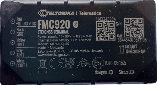
The FMC920 is a high-performance, low-power analog-to-digital converter (ADC) manufactured by Teltonika. Designed for precision data acquisition and signal processing, the FMC920 offers a flexible interface and supports multiple input channels, making it ideal for complex measurement systems. Its compact design and robust performance make it suitable for a wide range of applications, including industrial automation, medical instrumentation, and environmental monitoring.
Explore Projects Built with FMC920


Explore Projects Built with FMC920
Common Applications and Use Cases
- Data acquisition systems
- Signal processing in industrial automation
- Medical instrumentation for precise measurements
- Environmental monitoring and sensor interfacing
- Embedded systems requiring multi-channel ADC functionality
Technical Specifications
Key Technical Details
| Parameter | Value |
|---|---|
| Manufacturer | Teltonika |
| Part ID | GPS |
| Resolution | 12-bit |
| Number of Input Channels | 4 |
| Input Voltage Range | 0–5 V |
| Sampling Rate | Up to 1 MSPS (Mega Samples Per Second) |
| Power Supply Voltage | 3.3 V or 5 V |
| Power Consumption | < 10 mW |
| Operating Temperature | -40°C to +85°C |
| Interface | SPI (Serial Peripheral Interface) |
Pin Configuration and Descriptions
| Pin Number | Pin Name | Description |
|---|---|---|
| 1 | VCC | Power supply input (3.3 V or 5 V) |
| 2 | GND | Ground connection |
| 3 | CH1 | Analog input channel 1 |
| 4 | CH2 | Analog input channel 2 |
| 5 | CH3 | Analog input channel 3 |
| 6 | CH4 | Analog input channel 4 |
| 7 | SCLK | SPI clock input |
| 8 | MISO | SPI data output (Master In Slave Out) |
| 9 | MOSI | SPI data input (Master Out Slave In) |
| 10 | CS | Chip select (active low) |
Usage Instructions
How to Use the FMC920 in a Circuit
- Power Supply: Connect the VCC pin to a 3.3 V or 5 V power source and the GND pin to the ground.
- Analog Inputs: Connect the analog signals to the input channels (CH1–CH4). Ensure the input voltage does not exceed the specified range (0–5 V).
- SPI Interface: Connect the SPI pins (SCLK, MISO, MOSI, and CS) to the corresponding pins on your microcontroller or processor.
- Configuration: Use the SPI interface to configure the ADC settings, such as sampling rate and channel selection.
Important Considerations and Best Practices
- Input Voltage Protection: Use a voltage divider or clamping diodes to ensure the input voltage remains within the 0–5 V range.
- Decoupling Capacitors: Place a 0.1 µF ceramic capacitor close to the VCC pin to reduce power supply noise.
- Grounding: Ensure a solid ground connection to minimize noise and improve signal integrity.
- SPI Communication: Use proper pull-up or pull-down resistors on the SPI lines if required by your microcontroller.
Example Code for Arduino UNO
Below is an example of how to interface the FMC920 with an Arduino UNO using the SPI library:
#include <SPI.h>

// Define SPI pins for the FMC920
const int CS_PIN = 10; // Chip select pin for the ADC

void setup() {
  // Initialize serial communication for debugging
  Serial.begin(9600);

  // Set up SPI communication
  SPI.begin();
  pinMode(CS_PIN, OUTPUT);
  digitalWrite(CS_PIN, HIGH); // Set CS pin to inactive state

  Serial.println("FMC920 ADC Initialized");
}

void loop() {
  // Select the ADC by pulling CS low
  digitalWrite(CS_PIN, LOW);

  // Send a command to read from channel 1 (example command: 0x01)
  byte command = 0x01; // Replace with actual command for your application
  SPI.transfer(command);

  // Read the ADC data (12-bit result split into two bytes)
  byte highByte = SPI.transfer(0x00); // Read high byte
  byte lowByte = SPI.transfer(0x00);  // Read low byte

  // Combine the two bytes into a 12-bit result
  int adcValue = (highByte << 8) | lowByte;

  // Deselect the ADC by pulling CS high
  digitalWrite(CS_PIN, HIGH);

  // Print the ADC value to the serial monitor
  Serial.print("ADC Value: ");
  Serial.println(adcValue);

  delay(1000); // Wait for 1 second before the next reading
}
Troubleshooting and FAQs
Common Issues and Solutions
No Output or Incorrect Readings
- Cause: Incorrect SPI connections or configuration.
- Solution: Verify the SPI connections (SCLK, MISO, MOSI, and CS) and ensure the SPI settings (clock speed, mode) match the FMC920's requirements.
Noise in ADC Readings
- Cause: Power supply noise or poor grounding.
- Solution: Add decoupling capacitors near the VCC pin and ensure a solid ground connection.
Overvoltage on Input Channels
- Cause: Input voltage exceeds the 0–5 V range.
- Solution: Use a voltage divider or clamping diodes to protect the input channels.
SPI Communication Fails
- Cause: Incorrect chip select (CS) handling.
- Solution: Ensure the CS pin is pulled low before sending commands and pulled high after communication.
FAQs
Q: Can the FMC920 operate at 3.3 V?
A: Yes, the FMC920 supports both 3.3 V and 5 V power supply levels.
Q: What is the maximum sampling rate of the FMC920?
A: The FMC920 supports a maximum sampling rate of 1 MSPS.
Q: How many channels can be used simultaneously?
A: The FMC920 has 4 input channels, but only one channel can be sampled at a time.
Q: Is the FMC920 compatible with Arduino boards?
A: Yes, the FMC920 can be interfaced with Arduino boards using the SPI interface.