Cirkit Designer Logo
Cirkit Designer
Your all-in-one circuit design IDE
Home / 
Component Documentation

How to Use Female BNC: Examples, Pinouts, and Specs

Image of Female BNC
Cirkit Designer LogoDesign with Female BNC in Cirkit Designer

Introduction

The Female BNC (Bayonet Neill-Concelman) connector is a widely used coaxial RF connector suitable for quick connect and disconnect applications. It is commonly utilized in radio, television, and other radio-frequency electronic equipment, test instruments, video signals, and was once a popular connector for Ethernet networks. Its bayonet-style locking mechanism ensures a stable and reliable connection, which is essential for maintaining signal integrity in RF systems.

Explore Projects Built with Female BNC
Use Cirkit Designer to design, explore, and prototype these projects online. Some projects support real-time simulation. Click "Open Project" to start designing instantly!
Satellite Compass and Network-Integrated GPS Data Processing System
Image of GPS 시스템 측정 구성도_241016: A project utilizing Female BNC in a practical application
This circuit comprises a satellite compass, a mini PC, two GPS antennas, power supplies, a network switch, media converters, and an atomic rubidium clock. The satellite compass is powered by a triple output DC power supply and interfaces with an RS232 splitter for 1PPS signals. The mini PCs are connected to the USRP B200 devices via USB for data and power, and to media converters via Ethernet, which in turn connect to a network switch using fiber optic links. The antennas are connected to the USRP B200s through RF directional couplers, and the atomic clock provides a 1PPS input to the RS232 splitter.
Cirkit Designer LogoOpen Project in Cirkit Designer
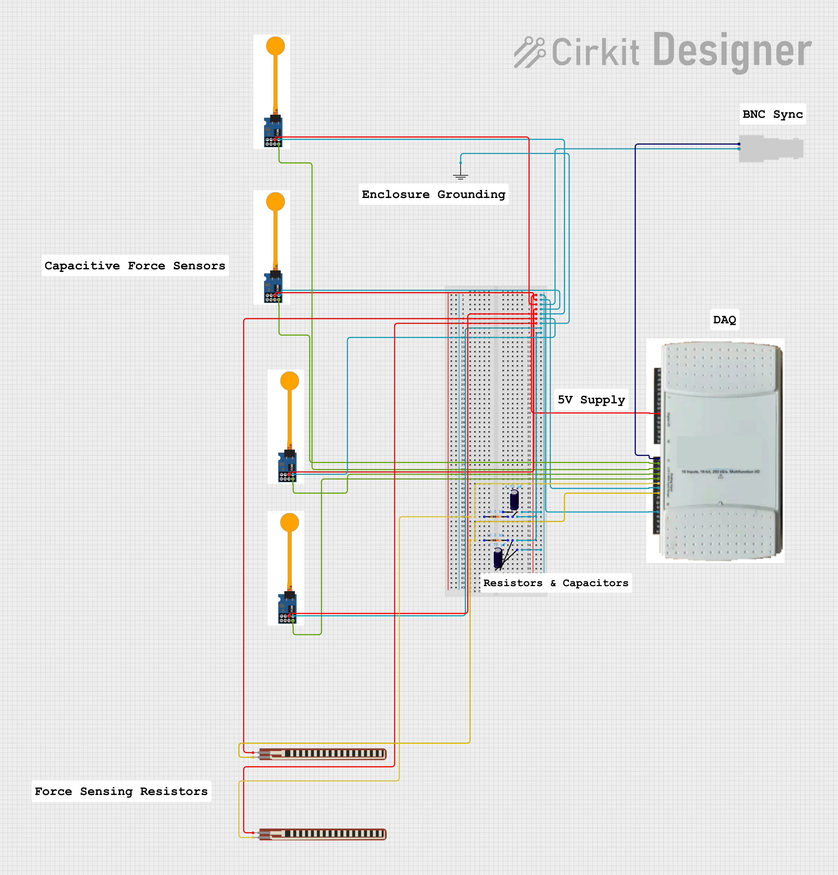
Capacitive Force Sensor Data Acquisition System with Flex Resistors
Image of Thin Force Sensors: A project utilizing Female BNC in a practical application
This circuit is designed to interface multiple capacitive force sensors and flex resistors with a Data Acquisition (DAQ) system. The sensors and resistors are connected through various resistors and capacitors to the DAQ, which collects and processes the sensor data. A Female BNC connector is also included for external signal input or output.
Cirkit Designer LogoOpen Project in Cirkit Designer
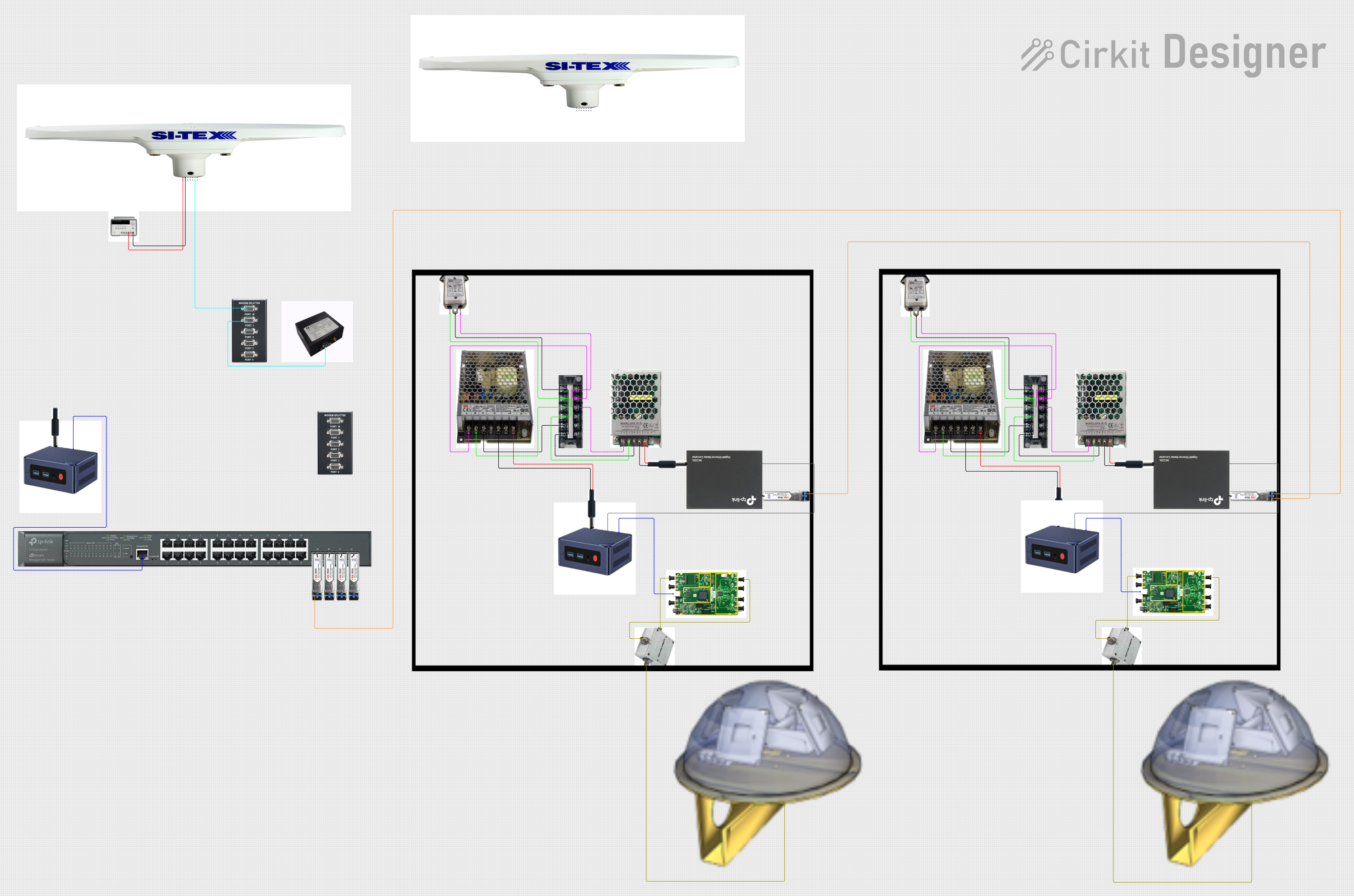
Satellite-Based Timing and Navigation System with SDR and Atomic Clock Synchronization
Image of GPS 시스템 측정 구성도_Confirm: A project utilizing Female BNC in a practical application
This circuit appears to be a complex system involving power supply management, GPS and timing synchronization, and data communication. It includes a SI-TEX G1 Satellite Compass for GPS data, an XHTF1021 Atomic Rubidium Clock for precise timing, and Ettus USRP B200 units for software-defined radio communication. Power is supplied through various SMPS units and distributed via terminal blocks and DC jacks. Data communication is facilitated by Beelink MINI S12 N95 computers, RS232 splitters, and a 1000BASE-T Media Converter for network connectivity. RF Directional Couplers are used to interface antennas with the USRP units, and the entire system is likely contained within cases for protection and organization.
Cirkit Designer LogoOpen Project in Cirkit Designer
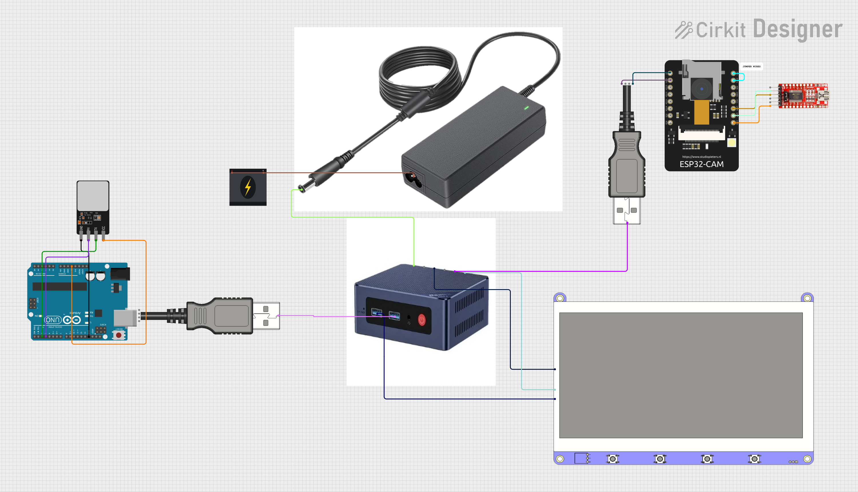
Beelink Mini S12 N95 and Arduino UNO Based Fingerprint Authentication System with ESP32 CAM
Image of design 3: A project utilizing Female BNC in a practical application
This circuit features a Beelink MINI S12 N95 computer connected to a 7-inch display via HDMI for video output and two USB connections for power and touch screen functionality. An Arduino UNO is interfaced with a fingerprint scanner for biometric input. The Beelink MINI S12 N95 is powered by a PC power supply, which in turn is connected to a 240V power source. Additionally, an ESP32 CAM module is powered and programmed via a USB plug and an FTDI programmer, respectively, for wireless camera capabilities.
Cirkit Designer LogoOpen Project in Cirkit Designer

Explore Projects Built with Female BNC

Use Cirkit Designer to design, explore, and prototype these projects online. Some projects support real-time simulation. Click "Open Project" to start designing instantly!
Image of GPS 시스템 측정 구성도_241016: A project utilizing Female BNC in a practical application
Satellite Compass and Network-Integrated GPS Data Processing System
This circuit comprises a satellite compass, a mini PC, two GPS antennas, power supplies, a network switch, media converters, and an atomic rubidium clock. The satellite compass is powered by a triple output DC power supply and interfaces with an RS232 splitter for 1PPS signals. The mini PCs are connected to the USRP B200 devices via USB for data and power, and to media converters via Ethernet, which in turn connect to a network switch using fiber optic links. The antennas are connected to the USRP B200s through RF directional couplers, and the atomic clock provides a 1PPS input to the RS232 splitter.
Cirkit Designer LogoOpen Project in Cirkit Designer
Image of Thin Force Sensors: A project utilizing Female BNC in a practical application
Capacitive Force Sensor Data Acquisition System with Flex Resistors
This circuit is designed to interface multiple capacitive force sensors and flex resistors with a Data Acquisition (DAQ) system. The sensors and resistors are connected through various resistors and capacitors to the DAQ, which collects and processes the sensor data. A Female BNC connector is also included for external signal input or output.
Cirkit Designer LogoOpen Project in Cirkit Designer
Image of GPS 시스템 측정 구성도_Confirm: A project utilizing Female BNC in a practical application
Satellite-Based Timing and Navigation System with SDR and Atomic Clock Synchronization
This circuit appears to be a complex system involving power supply management, GPS and timing synchronization, and data communication. It includes a SI-TEX G1 Satellite Compass for GPS data, an XHTF1021 Atomic Rubidium Clock for precise timing, and Ettus USRP B200 units for software-defined radio communication. Power is supplied through various SMPS units and distributed via terminal blocks and DC jacks. Data communication is facilitated by Beelink MINI S12 N95 computers, RS232 splitters, and a 1000BASE-T Media Converter for network connectivity. RF Directional Couplers are used to interface antennas with the USRP units, and the entire system is likely contained within cases for protection and organization.
Cirkit Designer LogoOpen Project in Cirkit Designer
Image of design 3: A project utilizing Female BNC in a practical application
Beelink Mini S12 N95 and Arduino UNO Based Fingerprint Authentication System with ESP32 CAM
This circuit features a Beelink MINI S12 N95 computer connected to a 7-inch display via HDMI for video output and two USB connections for power and touch screen functionality. An Arduino UNO is interfaced with a fingerprint scanner for biometric input. The Beelink MINI S12 N95 is powered by a PC power supply, which in turn is connected to a 240V power source. Additionally, an ESP32 CAM module is powered and programmed via a USB plug and an FTDI programmer, respectively, for wireless camera capabilities.
Cirkit Designer LogoOpen Project in Cirkit Designer

Technical Specifications

General Characteristics

  • Impedance: Typically 50 ohms or 75 ohms (depending on the design)
  • Frequency Range: Up to 4 GHz for 50 ohms, typically up to 2 GHz for 75 ohms
  • Voltage Rating: 500 volts peak
  • Body: Brass with nickel plating
  • Center Contact: Beryllium copper, gold or silver plating
  • Dielectric Type: PTFE
  • Durability (Mating cycles): ≥ 500 cycles

Pin Configuration and Descriptions

Pin Number Description Material Plating
1 Outer Conductor Brass Nickel
2 Inner Conductor Beryllium copper Gold/Silver
3 Insulator PTFE N/A

Note: The pin configuration table is a simplified representation. The Female BNC connector is a two-conductor design with an outer conductor (shield) and an inner conductor (signal).

Usage Instructions

Integration into a Circuit

  1. Cable Preparation: Strip the coaxial cable to expose the inner conductor and the shield without damaging the conductors.
  2. Soldering: Solder the center conductor to the center pin of the BNC connector and the shield to the outer conductor. Ensure a good-quality solder joint to maintain signal integrity.
  3. Connection: Align the notches of the Female BNC connector with the male connector's bayonet pins, insert, and twist to lock.
  4. Testing: After installation, always test the connection with appropriate equipment to ensure there are no shorts or open circuits.

Best Practices

  • Use the correct impedance connector (50 ohms or 75 ohms) to match the cable and equipment.
  • Avoid over-tightening the bayonet coupling to prevent damage.
  • Ensure that the cable is properly supported to avoid stress on the connector.
  • Keep connectors free of dust and other contaminants to maintain good electrical contact.

Troubleshooting and FAQs

Common Issues

  • Poor Signal Quality: Check for any loose connections or poor solder joints. Ensure the use of the correct impedance connector.
  • Physical Damage: Inspect the connector for any physical damage that might affect performance. Replace if necessary.
  • Intermittent Connection: Ensure that the connector is fully engaged with a firm twist and that there is no debris or damage preventing a good connection.

FAQs

Q: Can I use a 50-ohm BNC connector with a 75-ohm system? A: It is not recommended as it may lead to signal reflection and loss.

Q: How do I know if my BNC connector is 50 ohms or 75 ohms? A: Typically, the connector's impedance is marked on its body. If not, refer to the manufacturer's datasheet.

Q: Are BNC connectors suitable for high-frequency applications? A: BNC connectors are suitable for applications up to 4 GHz for 50 ohms and typically up to 2 GHz for 75 ohms.

Q: How do I prevent the BNC connector from coming loose? A: Ensure that the bayonet locking mechanism is fully engaged and check for wear and tear regularly.

Example Arduino UNO Connection

The Female BNC connector is not directly connected to an Arduino UNO but is used to connect RF equipment or antennas to modules that can interface with an Arduino. Below is an example of how to connect an RF module with a BNC connector to an Arduino UNO:

// Example code to initialize an RF module connected to an Arduino UNO
// This is a conceptual example and may not work with all RF modules.

#include <SPI.h> // Include the SPI library for communication

void setup() {
  // Initialize serial communication for debugging
  Serial.begin(9600);
  
  // Set up the RF module's communication pins
  pinMode(SS, OUTPUT); // Slave Select pin for the SPI interface
  SPI.begin(); // Begin SPI communication
}

void loop() {
  // Example code to send data through the RF module
  // Replace with actual data and commands for your specific RF module
  SPI.beginTransaction(SPISettings(4000000, MSBFIRST, SPI_MODE0));
  digitalWrite(SS, LOW); // Select the RF module
  SPI.transfer(0x00); // Send a byte of data
  digitalWrite(SS, HIGH); // Deselect the RF module
  SPI.endTransaction();
  
  delay(1000); // Wait for a second before sending the next byte
}

Note: The above code is for illustrative purposes only. The actual implementation will vary based on the specific RF module and its communication protocol.

Remember to consult the datasheet of the RF module for the correct pin connections and communication protocols. The BNC connector itself does not interface with the Arduino but serves as a connection point for the coaxial cable coming from the RF equipment.