How to Use Adafruit RTC DS3231: Examples, Pinouts, and Specs
Introduction
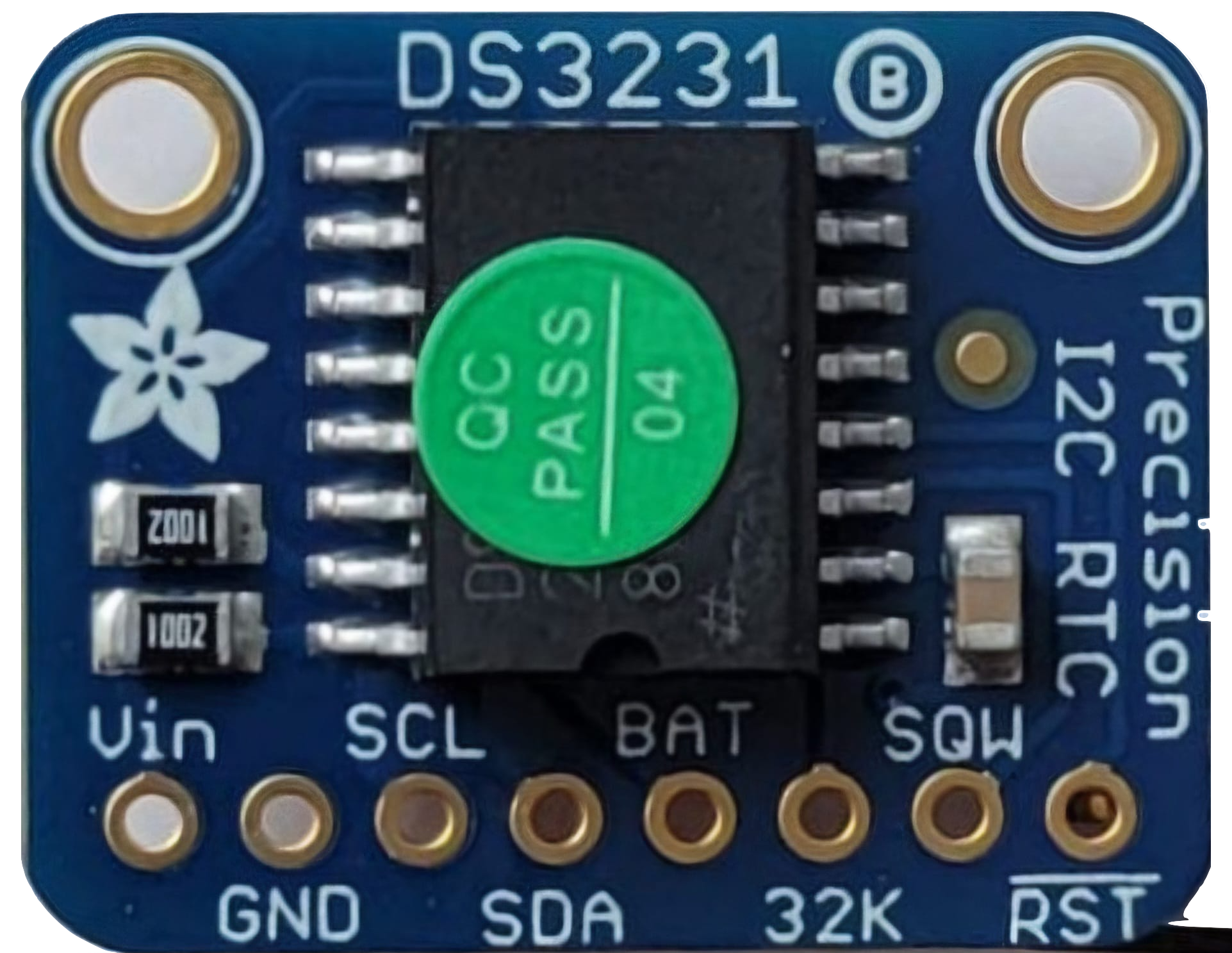
The Adafruit RTC DS3231 is a highly accurate real-time clock (RTC) module designed to keep track of the current time and date, even during power outages. It features an integrated temperature-compensated crystal oscillator (TCXO) to ensure high precision and low drift over time. The DS3231 is ideal for applications requiring precise timekeeping, such as data logging, alarms, and scheduling tasks in embedded systems. Its low power consumption makes it particularly suitable for battery-powered projects.
Explore Projects Built with Adafruit RTC DS3231


Explore Projects Built with Adafruit RTC DS3231
Common Applications
- Data logging systems
- Alarm clocks and timers
- IoT devices requiring time synchronization
- Scheduling and automation in embedded systems
- Battery-powered devices with long-term timekeeping needs
Technical Specifications
The Adafruit RTC DS3231 module offers the following key technical details:
| Parameter | Value |
|---|---|
| Supply Voltage | 2.3V to 5.5V |
| Timekeeping Current | 3.5 µA (at 3.3V, typical) |
| Temperature Accuracy | ±3°C |
| Timekeeping Accuracy | ±2 ppm (0°C to +40°C) |
| Communication Interface | I2C (Inter-Integrated Circuit) |
| Operating Temperature | -40°C to +85°C |
| Backup Battery Support | CR2032 coin cell (not included) |
Pin Configuration and Descriptions
The DS3231 module has the following pinout:
| Pin | Name | Description |
|---|---|---|
| 1 | GND | Ground connection |
| 2 | VCC | Power supply input (2.3V to 5.5V) |
| 3 | SDA | I2C data line for communication with the microcontroller |
| 4 | SCL | I2C clock line for communication with the microcontroller |
| 5 | SQW | Square wave output (optional, can be used for alarms or periodic interrupts) |
| 6 | 32K | 32.768 kHz output (optional, for external clocking purposes) |
Usage Instructions
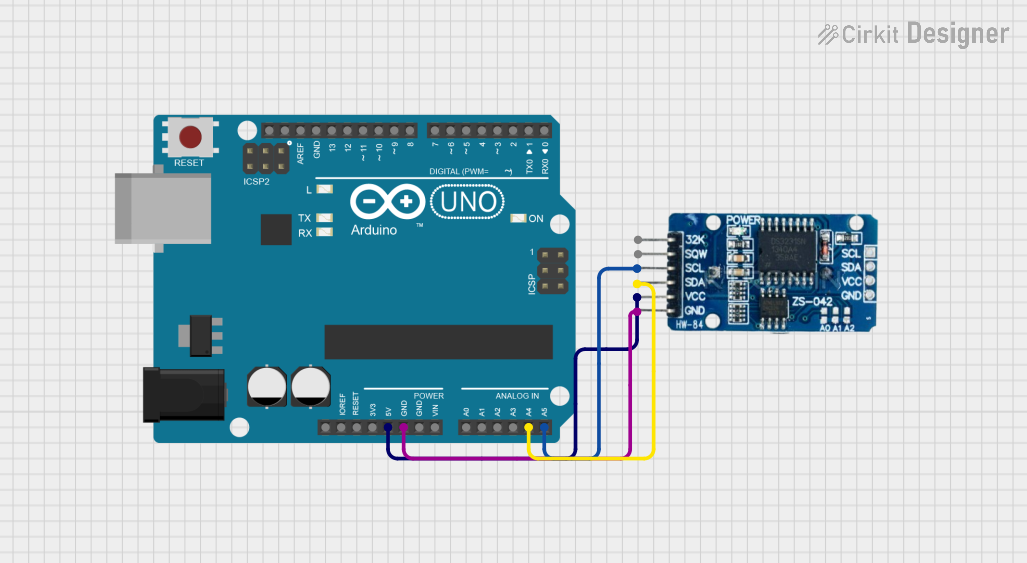
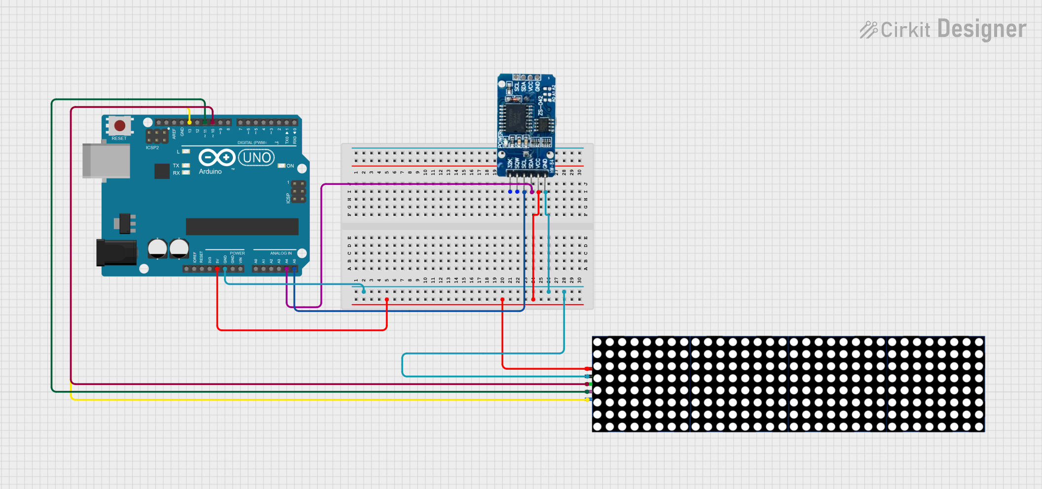
How to Use the DS3231 in a Circuit
- Power the Module: Connect the
VCCpin to a 3.3V or 5V power source and theGNDpin to ground. - I2C Communication: Connect the
SDAandSCLpins to the corresponding I2C pins on your microcontroller. For an Arduino UNO:SDAconnects to A4.SCLconnects to A5.
- Backup Battery: Insert a CR2032 coin cell battery into the battery holder to enable timekeeping during power loss.
- Optional Outputs:
- Use the
SQWpin for square wave or alarm signals. - Use the
32Kpin for an external 32.768 kHz clock signal if needed.
- Use the
Important Considerations
- Ensure pull-up resistors (typically 4.7kΩ) are connected to the
SDAandSCLlines if your microcontroller does not have internal pull-ups. - Avoid shorting the battery holder terminals to prevent damage to the module.
- The module's I2C address is
0x68by default.
Example Code for Arduino UNO
Below is an example of how to use the DS3231 with an Arduino UNO to read the current time and date. This code uses the popular RTClib library.
#include <Wire.h>
#include <RTClib.h>

// Create an RTC_DS3231 object to interact with the module
RTC_DS3231 rtc;

void setup() {
  Serial.begin(9600); // Initialize serial communication at 9600 baud
  Wire.begin();       // Initialize I2C communication

  // Check if the RTC is connected and working
  if (!rtc.begin()) {
    Serial.println("Couldn't find RTC. Check connections!");
    while (1); // Halt the program if RTC is not found
  }

  // Check if the RTC lost power and set the time if necessary
  if (rtc.lostPower()) {
    Serial.println("RTC lost power, setting the time!");
    // Set the RTC to the current date and time
    rtc.adjust(DateTime(F(__DATE__), F(__TIME__)));
  }
}

void loop() {
  // Get the current date and time from the RTC
  DateTime now = rtc.now();

  // Print the current date and time to the Serial Monitor
  Serial.print(now.year(), DEC);
  Serial.print('/');
  Serial.print(now.month(), DEC);
  Serial.print('/');
  Serial.print(now.day(), DEC);
  Serial.print(" ");
  Serial.print(now.hour(), DEC);
  Serial.print(':');
  Serial.print(now.minute(), DEC);
  Serial.print(':');
  Serial.print(now.second(), DEC);
  Serial.println();

  delay(1000); // Wait for 1 second before updating
}
Best Practices
- Always use a fresh CR2032 battery to ensure reliable backup power.
- Avoid handling the module with bare hands to prevent static discharge damage.
- Use proper decoupling capacitors near the power supply pins for stable operation.
Troubleshooting and FAQs
Common Issues and Solutions
RTC Not Detected:
- Cause: Incorrect wiring or I2C address mismatch.
- Solution: Verify the
SDAandSCLconnections. Ensure the I2C address is set to0x68.
Incorrect Time or Date:
- Cause: RTC lost power or was not initialized properly.
- Solution: Check the backup battery and reinitialize the RTC using the
rtc.adjust()function.
No Output on Serial Monitor:
- Cause: Serial communication not initialized or incorrect baud rate.
- Solution: Ensure
Serial.begin(9600)is called insetup()and the Serial Monitor is set to 9600 baud.
Square Wave Output Not Working:
- Cause: SQW pin not configured.
- Solution: Use the appropriate library functions to enable and configure the square wave output.
FAQs
Q: Can the DS3231 module work without a backup battery?
A: Yes, but it will lose track of time when the main power is disconnected.
Q: What is the default I2C address of the DS3231?
A: The default I2C address is 0x68.
Q: Can I use the DS3231 with a 3.3V microcontroller?
A: Yes, the DS3231 supports a supply voltage range of 2.3V to 5.5V, making it compatible with both 3.3V and 5V systems.
Q: How accurate is the DS3231?
A: The DS3231 has an accuracy of ±2 ppm, which translates to a drift of about ±1 minute per year under typical conditions.