The 5408 Diode is a robust standard switching diode widely used in electronic circuits. It is designed to handle relatively high voltages and currents, making it suitable for rectification, signal processing, and power regulation applications. Its reliability and efficiency make it a popular choice for both hobbyists and professionals.
Explore Projects Built with 5408 Diode
Use Cirkit Designer to design, explore, and prototype these projects online. Some projects support real-time simulation. Click "Open Project" to start designing instantly!
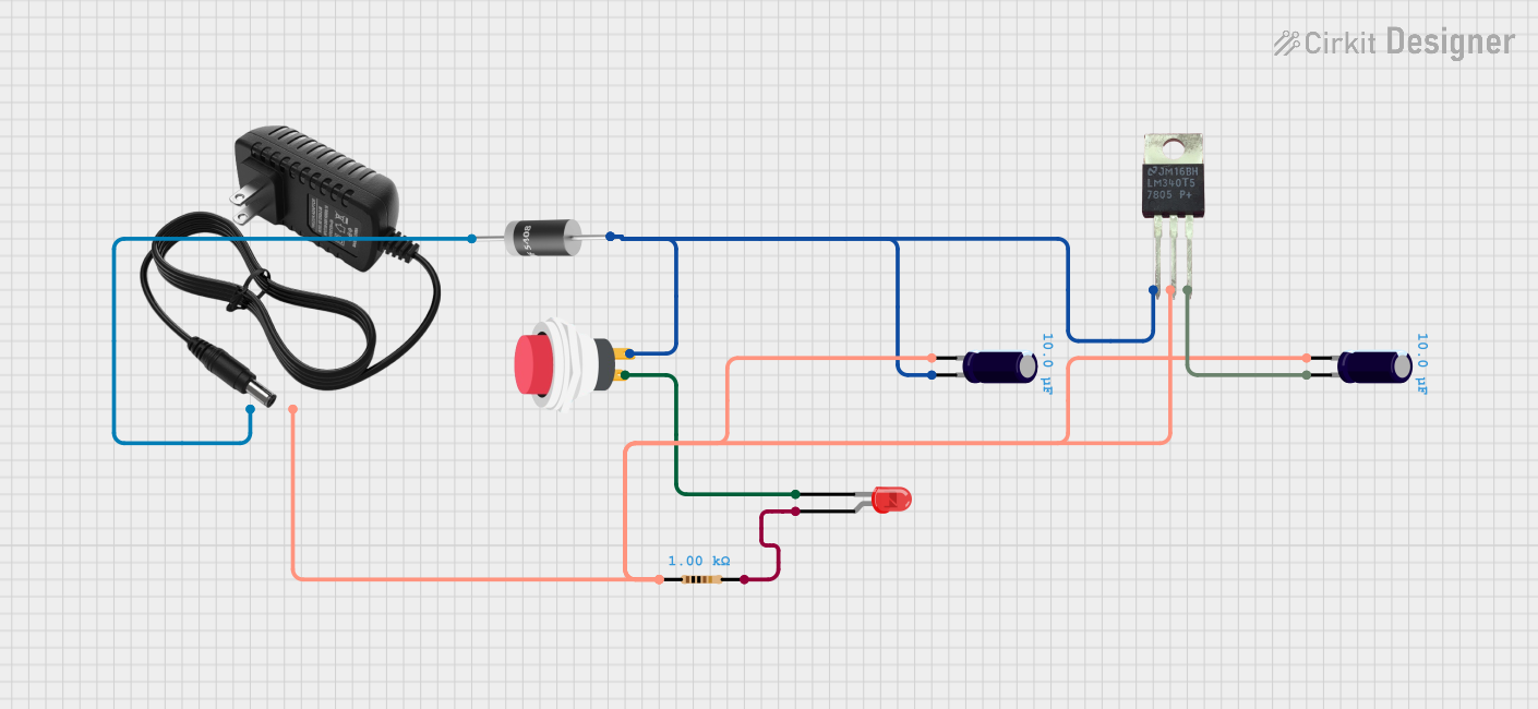
This circuit is a 12V to 5V regulated power supply with an LED indicator. It uses a 5408 diode for reverse polarity protection, an LM340T5 7805 voltage regulator to step down the voltage to 5V, and a push switch to control the LED indicator. The circuit also includes capacitors for filtering and a resistor to limit the current through the LED.
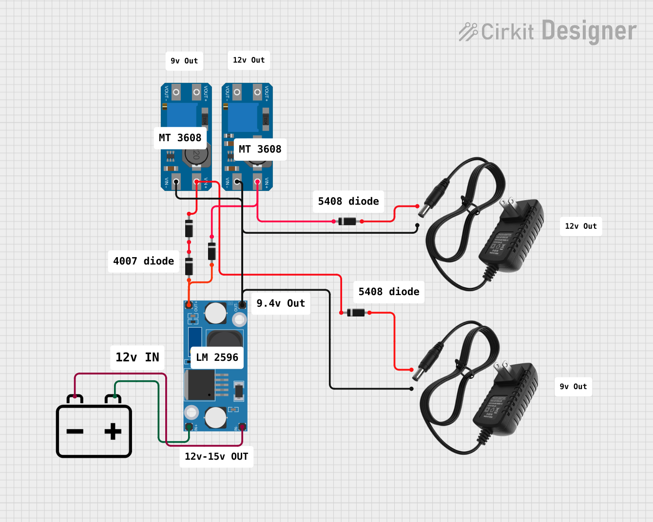
This circuit consists of two MT3608 boost converters and an LM2596 step-down module, each connected to separate 12V power supplies. The MT3608 modules are configured to step up the voltage from their respective power supplies, while the LM2596 module steps down the voltage from a 12V battery. Diodes are used to ensure correct current flow direction, potentially for protection or isolation between different parts of the circuit.
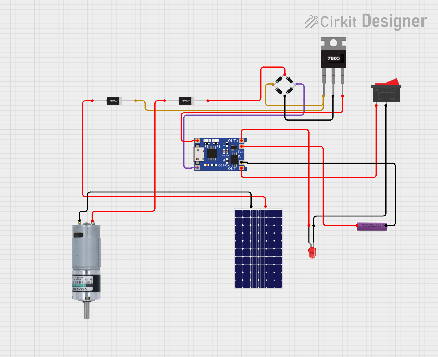
This circuit appears to be a solar-powered charging and power supply system with a battery backup. A TP4056 module is used for charging the 3.7V battery from the solar panel via a bridge rectifier, ensuring proper battery management. The system can power an LED and a motor, with a rocker switch to control the LED, and diodes are used to provide correct polarity and prevent backflow of current.
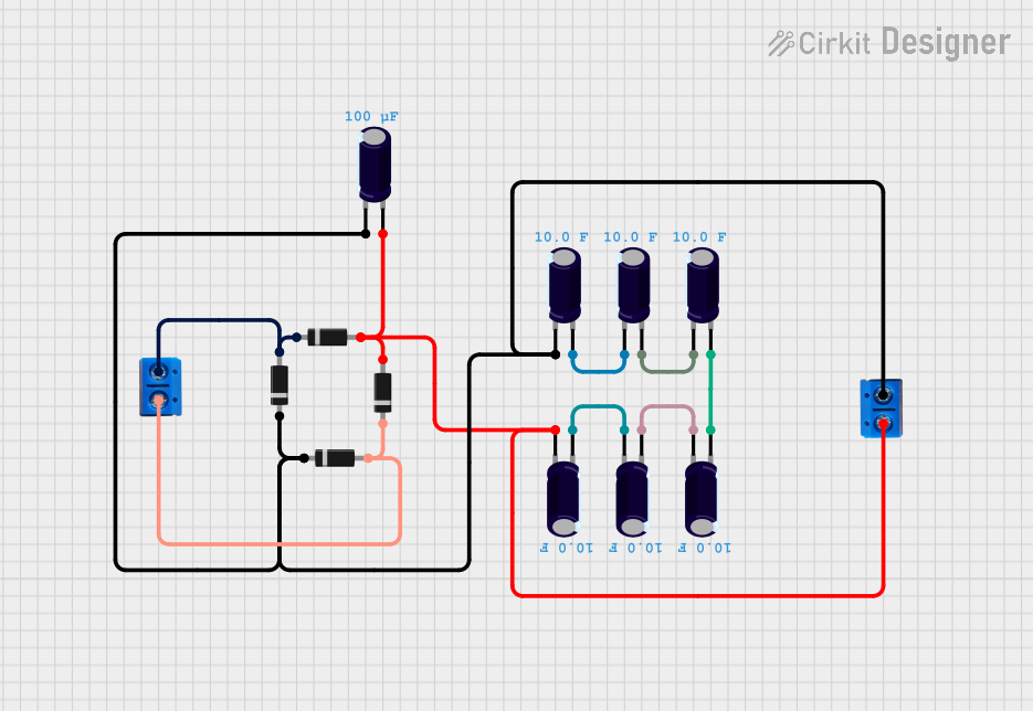
This circuit is a complex network of diodes and electrolytic capacitors connected to two terminal PCB 2-pin connectors. The diodes are arranged in a series-parallel configuration, while the capacitors are connected in a manner that suggests filtering or energy storage purposes. The overall design appears to be aimed at rectification and smoothing of an input signal.
The 5408 Diode is characterized by its ability to withstand high reverse voltages and its fast switching capabilities. Below are the key technical specifications:
Parameter
Value
Maximum Repetitive Reverse Voltage (Vrrm)
1000 V
Average Rectified Forward Current (Io)
3 A
Non-Repetitive Peak Forward Surge Current (Ifsm)
200 A
Forward Voltage Drop (Vf)
1.2 V @ 3 A
Reverse Current (Ir)
5 µA @ 1000 V
Operating Junction Temperature (Tj)
-65 to 175 °C
Pin Configuration and Descriptions
The 5408 Diode has a simple two-pin configuration:
Pin
Description
Anode (A)
The positive side of the diode, where current enters
Cathode (K)
The negative side of the diode, where current exits
Usage Instructions
How to Use the 5408 Diode in a Circuit
Identify the Anode and Cathode: The anode is typically marked by a stripe on the diode's body.
Direction of Current: Ensure the diode is oriented so that the anode is connected to the positive voltage and the cathode to the negative side.
Current Rating: Do not exceed the average rectified forward current rating of 3 A.
Voltage Rating: Ensure the reverse voltage does not exceed 1000 V.
Important Considerations and Best Practices
Heat Dissipation: The diode can generate heat during operation. Use a heat sink if necessary.
Reverse Voltage Protection: Always verify the maximum reverse voltage to prevent breakdown.
Surge Current: Be cautious of transient currents that can exceed the surge current rating.
Circuit Testing: Test the diode in a controlled environment before deploying it in a critical application.
Troubleshooting and FAQs
Common Issues
Diode Not Conducting: Ensure the diode is correctly oriented and that the anode is connected to the higher potential.
Excessive Heat: Check if the current exceeds the rated value or if proper heat sinking is required.
Unexpected Voltage Drops: Verify that the forward voltage drop is within the expected range for the current flowing through the diode.
Solutions and Tips
Diode Orientation: Use a multimeter to confirm the anode and cathode orientation if markings are unclear.
Heat Management: Implement proper heat sinking or reduce the load current to manage excessive heat.
Component Replacement: If the diode is suspected to be faulty, replace it with a new one and retest the circuit.
FAQs
Q: Can the 5408 Diode be used for AC to DC conversion?
A: Yes, it can be used in bridge rectifiers for AC to DC conversion.
Q: Is the 5408 Diode suitable for high-frequency applications?
A: While it can handle switching applications, there may be better-suited diodes for high-frequency purposes.
Q: What happens if the diode is exposed to a voltage higher than 1000 V?
A: The diode may undergo irreversible damage due to breakdown.
Q: Can I use multiple 5408 Diodes in parallel for higher current applications?
A: Yes, but ensure current sharing is balanced, possibly by using resistors.
Example Connection with Arduino UNO
The 5408 Diode can be used to protect an Arduino UNO from reverse voltage damage. Here's a simple example:
// No specific code is required for the diode itself, as it is a passive component.
// Below is an example setup where the diode is used to protect the Arduino from
// reverse voltage when powering it through the Vin pin.

void setup() {
  // Setup code here
}

void loop() {
  // Your main code would go here
}

// Connect the anode of the 5408 Diode to the external power supply's positive terminal.
// Connect the cathode of the diode to the Arduino's Vin pin.
// This ensures that if the power supply is accidentally reversed, the diode will block
// the current, protecting the Arduino from damage.
Remember, the diode does not require any code to function; it operates purely on the electrical level. The example above is to illustrate how the diode might be incorporated into an Arduino project for protection purposes.


 Open Project in Cirkit Designer