How to Use TB6612FNG Motor Driver: Examples, Pinouts, and Specs
Introduction
The TB6612FNG is a dual H-bridge motor driver IC designed to control two DC motors or one stepper motor. It supports PWM (Pulse Width Modulation) for precise speed control and direction management. With built-in thermal shutdown protection, overcurrent protection, and low standby current, the TB6612FNG is a reliable choice for robotics, automation, and other motor control applications.
Explore Projects Built with TB6612FNG Motor Driver

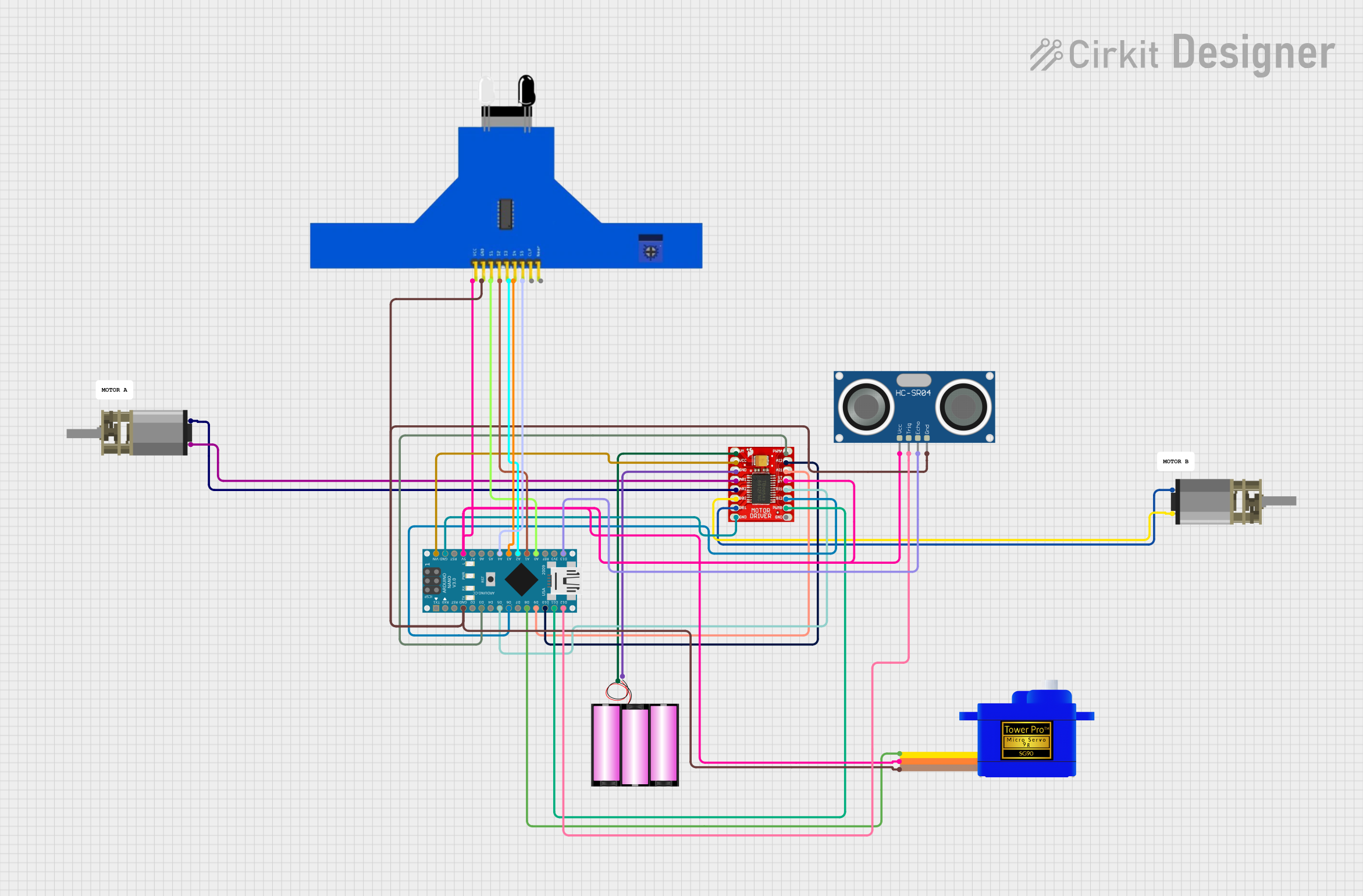
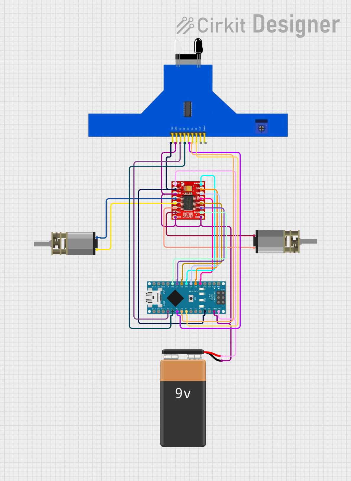
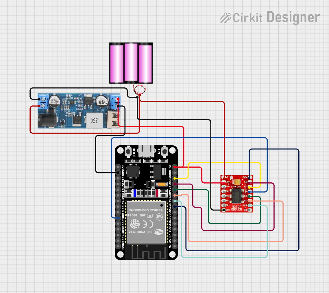
Explore Projects Built with TB6612FNG Motor Driver
Common Applications
- Robotics (e.g., controlling wheels or arms)
- Automated conveyor systems
- DIY projects involving DC or stepper motors
- Educational electronics kits
- Small-scale industrial automation
Technical Specifications
Key Technical Details
| Parameter | Value |
|---|---|
| Operating Voltage (Vcc) | 2.7V to 5.5V |
| Motor Voltage (VM) | 4.5V to 13.5V |
| Output Current (per channel) | 1.2A (continuous), 3.2A (peak) |
| Control Interface | PWM and digital signals |
| Standby Current | 1 µA (typical) |
| Built-in Protections | Thermal shutdown, overcurrent |
| Operating Temperature Range | -20°C to +85°C |
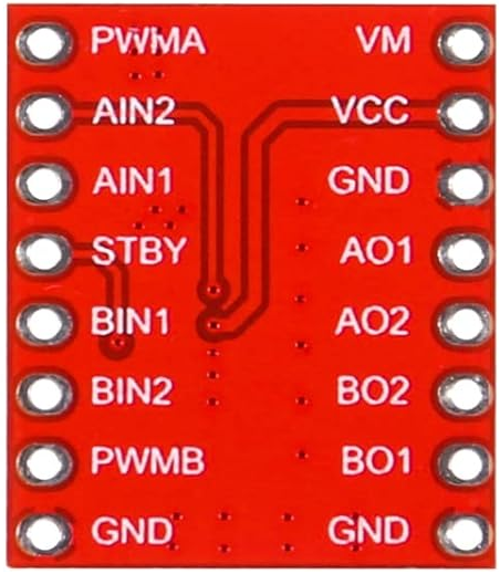
Pin Configuration and Descriptions
The TB6612FNG comes in a 16-pin package. Below is the pinout and description:
| Pin Number | Pin Name | Description |
|---|---|---|
| 1 | PWMA | PWM input for Motor A |
| 2 | AIN1 | Input 1 for Motor A (direction control) |
| 3 | AIN2 | Input 2 for Motor A (direction control) |
| 4 | STBY | Standby control (active HIGH to enable the IC) |
| 5 | Vcc | Logic power supply (2.7V to 5.5V) |
| 6 | AO1 | Output 1 for Motor A |
| 7 | AO2 | Output 2 for Motor A |
| 8 | VM | Motor power supply (4.5V to 13.5V) |
| 9 | BO2 | Output 2 for Motor B |
| 10 | BO1 | Output 1 for Motor B |
| 11 | GND | Ground |
| 12 | Vcc | Logic power supply (connected internally to Pin 5) |
| 13 | BIN2 | Input 2 for Motor B (direction control) |
| 14 | BIN1 | Input 1 for Motor B (direction control) |
| 15 | PWMB | PWM input for Motor B |
| 16 | NC | No connection |
Usage Instructions
How to Use the TB6612FNG in a Circuit
Power Connections:
- Connect
Vccto a 3.3V or 5V logic power supply. - Connect
VMto the motor power supply (4.5V to 13.5V). - Connect
GNDto the ground of the power supply.
- Connect
Motor Connections:
- Connect the motor terminals to
AO1andAO2for Motor A, andBO1andBO2for Motor B.
- Connect the motor terminals to
Control Signals:
- Use
AIN1andAIN2to control the direction of Motor A, andBIN1andBIN2for Motor B. - Provide PWM signals to
PWMAandPWMBto control the speed of Motor A and Motor B, respectively. - Set
STBYHIGH to enable the IC. Pull it LOW to put the IC in standby mode.
- Use
Direction Control:
- Set
AIN1HIGH andAIN2LOW to rotate Motor A in one direction. - Set
AIN1LOW andAIN2HIGH to rotate Motor A in the opposite direction. - Similarly, use
BIN1andBIN2for Motor B.
- Set
PWM Speed Control:
- Apply a PWM signal (0-100% duty cycle) to
PWMAorPWMBto control the speed of the motors.
- Apply a PWM signal (0-100% duty cycle) to
Example: Using TB6612FNG with Arduino UNO
Below is an example code to control two DC motors using the TB6612FNG and an Arduino UNO:
// Pin definitions for Motor A
const int AIN1 = 7;  // Direction control pin 1 for Motor A
const int AIN2 = 8;  // Direction control pin 2 for Motor A
const int PWMA = 9;  // PWM speed control pin for Motor A

// Pin definitions for Motor B
const int BIN1 = 4;  // Direction control pin 1 for Motor B
const int BIN2 = 5;  // Direction control pin 2 for Motor B
const int PWMB = 6;  // PWM speed control pin for Motor B

// Standby pin
const int STBY = 10; // Standby control pin

void setup() {
  // Set all pins as outputs
  pinMode(AIN1, OUTPUT);
  pinMode(AIN2, OUTPUT);
  pinMode(PWMA, OUTPUT);
  pinMode(BIN1, OUTPUT);
  pinMode(BIN2, OUTPUT);
  pinMode(PWMB, OUTPUT);
  pinMode(STBY, OUTPUT);

  // Enable the motor driver by setting STBY HIGH
  digitalWrite(STBY, HIGH);
}

void loop() {
  // Example: Rotate Motor A forward at 50% speed
  digitalWrite(AIN1, HIGH);
  digitalWrite(AIN2, LOW);
  analogWrite(PWMA, 128); // 50% duty cycle (128 out of 255)

  // Example: Rotate Motor B backward at 75% speed
  digitalWrite(BIN1, LOW);
  digitalWrite(BIN2, HIGH);
  analogWrite(PWMB, 192); // 75% duty cycle (192 out of 255)

  delay(2000); // Run motors for 2 seconds

  // Stop both motors
  analogWrite(PWMA, 0);
  analogWrite(PWMB, 0);

  delay(2000); // Wait for 2 seconds before repeating
}
Important Considerations
- Ensure that the motor power supply voltage (
VM) matches the motor's rated voltage. - Do not exceed the maximum continuous current rating of 1.2A per channel.
- Use appropriate decoupling capacitors between
VMandGNDto reduce noise. - Avoid running the IC at high currents for extended periods to prevent overheating.
Troubleshooting and FAQs
Common Issues and Solutions
Motors Not Running:
- Ensure
STBYis set HIGH to enable the IC. - Check the power supply connections for
VccandVM. - Verify that the PWM signals are being generated correctly.
- Ensure
Motor Running in the Wrong Direction:
- Swap the logic levels of
AIN1andAIN2(orBIN1andBIN2) to reverse the direction.
- Swap the logic levels of
Overheating:
- Ensure the current draw of the motors does not exceed 1.2A per channel.
- Add a heatsink or improve ventilation if the IC gets too hot.
No Response to PWM Signals:
- Verify that the PWM frequency is within the recommended range (typically 20kHz or lower).
- Check the connections to the
PWMAandPWMBpins.
FAQs
Q: Can the TB6612FNG drive stepper motors?
A: Yes, the TB6612FNG can drive a bipolar stepper motor by controlling the two H-bridges with appropriate step sequences.
Q: What happens if the IC overheats?
A: The TB6612FNG has built-in thermal shutdown protection. It will automatically disable the outputs if the temperature exceeds safe limits.
Q: Can I use the TB6612FNG with a 3.3V microcontroller?
A: Yes, the TB6612FNG supports logic levels as low as 2.7V, making it compatible with 3.3V microcontrollers.