How to Use RGB LED (Wokwi compatible): Examples, Pinouts, and Specs
Introduction
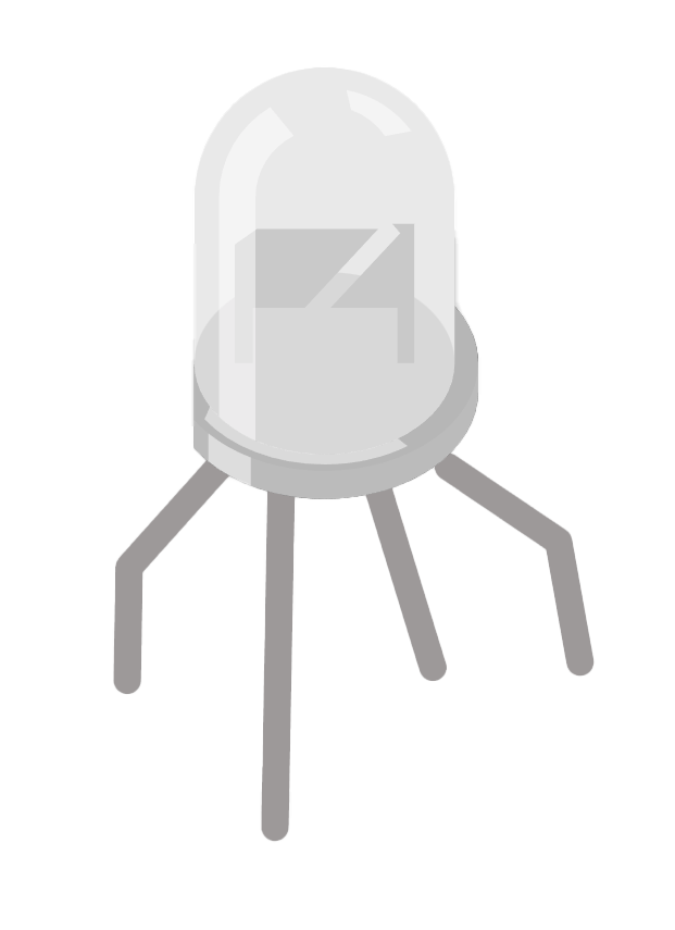
An RGB LED is a versatile electronic component that combines Red, Green, and Blue light-emitting diodes in a single package. By adjusting the intensity of each primary color, users can mix colors to produce a wide spectrum of hues, including white. This Wokwi compatible RGB LED is designed to interface easily with microcontrollers such as the Arduino UNO, making it ideal for a variety of applications including mood lighting, color displays, and indicators.
Explore Projects Built with RGB LED (Wokwi compatible)

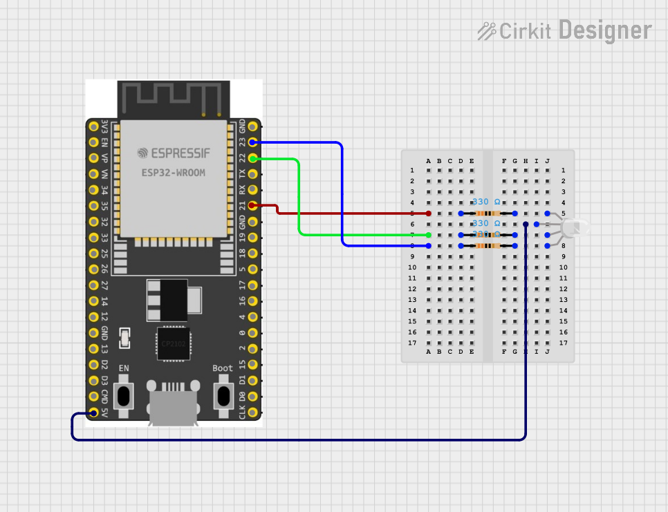
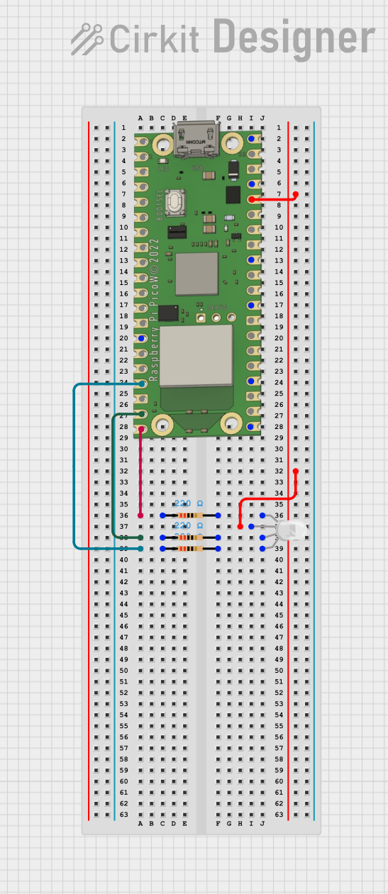
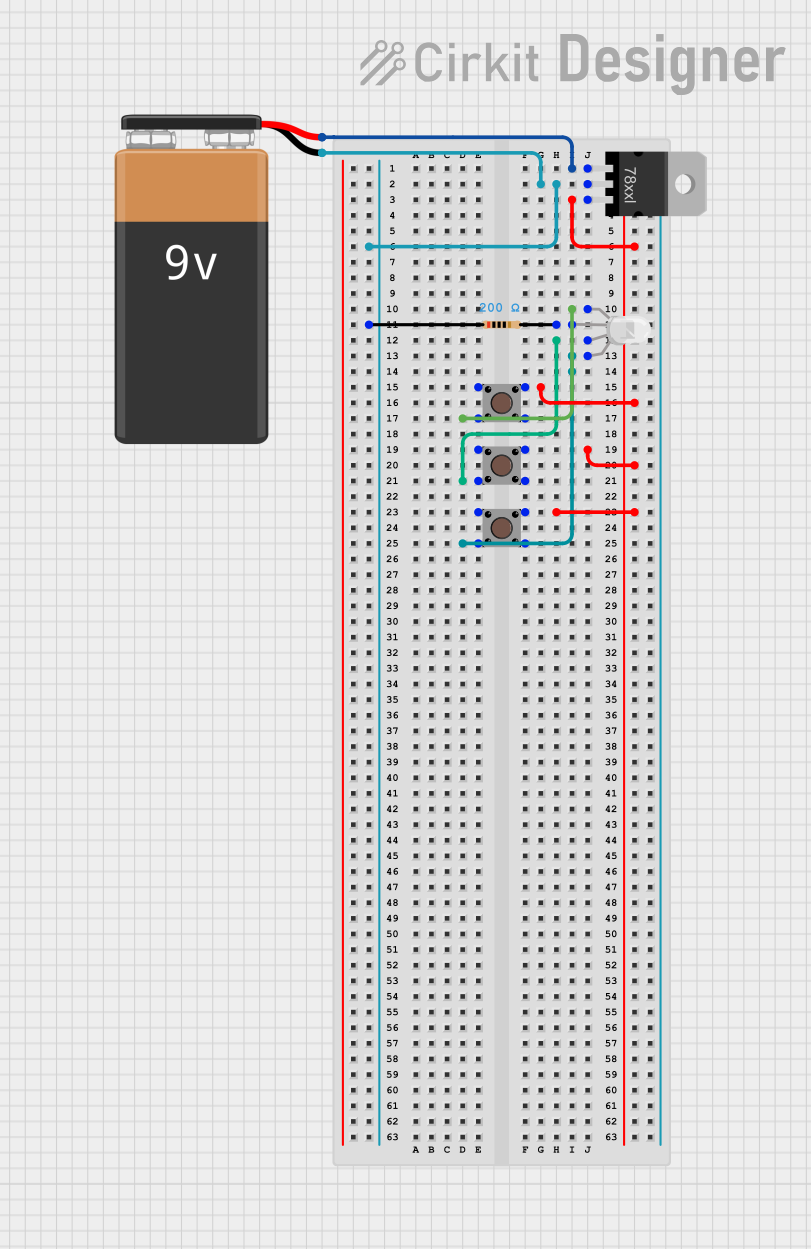
Explore Projects Built with RGB LED (Wokwi compatible)
Common Applications and Use Cases
- Decorative lighting
- Signal indicators
- Display panels
- Interactive art installations
- Educational projects to demonstrate color mixing
Technical Specifications
Key Technical Details
- Forward Voltage: Red: 1.8-2.2V, Green: 2.8-3.2V, Blue: 2.8-3.2V
- Forward Current: 20mA (typical) per color
- Luminous Intensity: Red: 600-800mcd, Green: 1500-2000mcd, Blue: 500-700mcd
- Viewing Angle: ~120 degrees
Pin Configuration and Descriptions
| Pin Number | Description | Color |
|---|---|---|
| 1 | Common Anode/Cathode* | - |
| 2 | Red Anode/Cathode | Red |
| 3 | Green Anode/Cathode | Green |
| 4 | Blue Anode/Cathode | Blue |
*Note: The common pin may be either an anode or cathode, depending on the model of the RGB LED. Ensure to check the datasheet of your specific component.
Usage Instructions
How to Use the Component in a Circuit
- Identify the Type: Determine if your RGB LED is common anode or common cathode.
- Connect the Common Pin: For common anode, connect the common pin to the positive supply voltage. For common cathode, connect it to ground.
- Resistor Selection: Choose appropriate resistors to limit the current for each color to 20mA. Use Ohm's law and the forward voltage values to calculate the resistor values.
- Microcontroller Connection: Connect the other pins (Red, Green, Blue) to the PWM-capable pins of the microcontroller.
- Programming: Use PWM signals to control the intensity of each color.
Important Considerations and Best Practices
- Always use current-limiting resistors to prevent damage to the LEDs.
- Avoid driving the LEDs with a current higher than the maximum rating.
- Use PWM (Pulse Width Modulation) to achieve color mixing and dimming effects.
- Ensure proper heat dissipation if operating multiple LEDs or at high brightness levels.
Example Code for Arduino UNO
// Define the RGB LED pins
const int RED_PIN = 9;    // Red LED pin
const int GREEN_PIN = 10; // Green LED pin
const int BLUE_PIN = 11;  // Blue LED pin

void setup() {
  // Set the LED pins as output
  pinMode(RED_PIN, OUTPUT);
  pinMode(GREEN_PIN, OUTPUT);
  pinMode(BLUE_PIN, OUTPUT);
}

void loop() {
  // Set the color to purple
  analogWrite(RED_PIN, 255);   // Red at full intensity
  analogWrite(GREEN_PIN, 0);   // Green off
  analogWrite(BLUE_PIN, 255);  // Blue at full intensity

  delay(1000); // Wait for 1 second

  // Set the color to a soft teal
  analogWrite(RED_PIN, 0);     // Red off
  analogWrite(GREEN_PIN, 128); // Green at half intensity
  analogWrite(BLUE_PIN, 128);  // Blue at half intensity

  delay(1000); // Wait for 1 second
}
Troubleshooting and FAQs
Common Issues Users Might Face
- LED Not Lighting Up: Check the polarity of the LED and ensure the common pin is correctly connected.
- Dim or Uneven Colors: Verify that the resistors are of the correct value and that the PWM signals are correctly configured.
- LED Burnout: Ensure that the current through the LED does not exceed the maximum rating.
Solutions and Tips for Troubleshooting
- Double-check wiring against the pin configuration.
- Use a multimeter to verify the voltage across and current through the LED.
- If using PWM, ensure the microcontroller's code is correctly generating the PWM signals.
FAQs
Q: Can I power the RGB LED directly from an Arduino pin? A: While you can power the LED from an Arduino pin, it is recommended to use a current-limiting resistor to prevent damage to both the LED and the microcontroller.
Q: How do I create white light with an RGB LED? A: To create white light, you need to turn on all three colors (Red, Green, Blue) at full intensity. Adjust the intensity if the white light appears to have a color tint.
Q: What is PWM and how does it control the LED color? A: PWM stands for Pulse Width Modulation. It controls the brightness of each LED by rapidly turning it on and off at a frequency high enough that the human eye perceives it as a continuous light with varying intensity. By adjusting the duty cycle (the percentage of time the signal is high), you can control the intensity of each color, thus mixing them to create different colors.