How to Use Power Board: Examples, Pinouts, and Specs
Introduction
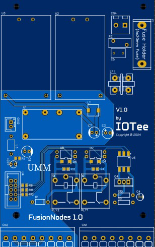
The FusionNodes Power Board by EIDOS Technologies is a versatile circuit board designed to distribute electrical power to various components in an electronic device. It includes essential features such as voltage regulation and protection, making it an ideal choice for both hobbyists and professionals working on complex electronic projects.
Explore Projects Built with Power Board

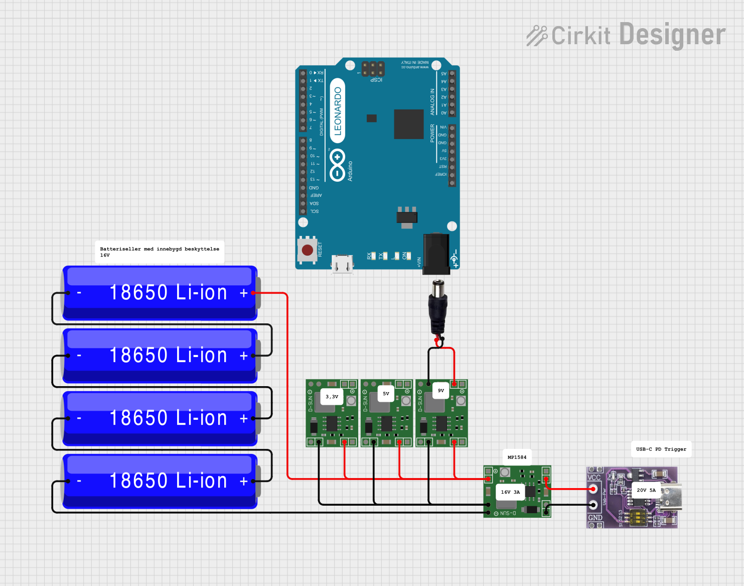


Explore Projects Built with Power Board
Common Applications and Use Cases
- Robotics: Powering multiple motors and sensors.
- IoT Devices: Distributing power to various modules and sensors.
- Prototyping: Providing a stable power supply for breadboard and development board projects.
- Embedded Systems: Ensuring reliable power distribution in custom embedded systems.
Technical Specifications
Key Technical Details
| Parameter | Value |
|---|---|
| Input Voltage | 7V - 24V |
| Output Voltage | 3.3V, 5V, 12V |
| Maximum Current | 3A per output |
| Power Rating | 36W |
| Protection Features | Overcurrent, Overvoltage, Short Circuit |
Pin Configuration and Descriptions
| Pin Number | Pin Name | Description |
|---|---|---|
| 1 | VIN | Input Voltage (7V - 24V) |
| 2 | GND | Ground |
| 3 | VOUT_3.3V | 3.3V Output |
| 4 | VOUT_5V | 5V Output |
| 5 | VOUT_12V | 12V Output |
| 6 | GND | Ground |
Usage Instructions
How to Use the FusionNodes Power Board in a Circuit
Connect the Input Voltage:
- Connect the VIN pin to your power source (7V - 24V).
- Connect the GND pin to the ground of your power source.
Distribute Power to Components:
- Use the VOUT_3.3V, VOUT_5V, and VOUT_12V pins to power your components.
- Ensure that the total current drawn from each output does not exceed 3A.
Ground Connections:
- Connect the GND pins to the ground of your components to complete the circuit.
Important Considerations and Best Practices
- Heat Dissipation: Ensure adequate ventilation or heat sinking if the board is operating near its maximum power rating.
- Current Limits: Do not exceed the maximum current rating of 3A per output to avoid damage.
- Polarity: Double-check the polarity of your connections to prevent short circuits or damage to the board.
Troubleshooting and FAQs
Common Issues and Solutions
No Output Voltage:
- Check Input Voltage: Ensure that the input voltage is within the specified range (7V - 24V).
- Verify Connections: Make sure all connections are secure and correctly oriented.
Overheating:
- Reduce Load: Ensure that the total current drawn does not exceed the maximum rating.
- Improve Ventilation: Provide adequate cooling or heat sinking.
Short Circuit Protection Triggered:
- Inspect Wiring: Check for any short circuits in your wiring.
- Reset Board: Disconnect and reconnect the power to reset the protection circuitry.
FAQs
Q: Can I use the FusionNodes Power Board with an Arduino UNO? A: Yes, you can use the FusionNodes Power Board to power an Arduino UNO. Connect the 5V output to the 5V pin on the Arduino and the GND to the ground pin.
Q: What happens if I exceed the maximum current rating? A: The board includes overcurrent protection, which will shut down the output to prevent damage. Reduce the load and reset the board.
Q: Can I use multiple output voltages simultaneously? A: Yes, you can use the 3.3V, 5V, and 12V outputs simultaneously, provided the total current drawn from each does not exceed 3A.
Example Code for Arduino UNO
Here is an example code to demonstrate how to use the FusionNodes Power Board to power an Arduino UNO and control an LED:
// Example code to control an LED using Arduino UNO powered by FusionNodes Power Board

const int ledPin = 13; // Pin connected to the LED

void setup() {
  pinMode(ledPin, OUTPUT); // Set the LED pin as an output
}

void loop() {
  digitalWrite(ledPin, HIGH); // Turn the LED on
  delay(1000);                // Wait for 1 second
  digitalWrite(ledPin, LOW);  // Turn the LED off
  delay(1000);                // Wait for 1 second
}
In this example, the Arduino UNO is powered by the 5V output from the FusionNodes Power Board. The code toggles an LED connected to pin 13 on and off every second.
This documentation provides a comprehensive guide to using the EIDOS Technologies FusionNodes Power Board. Whether you are a beginner or an experienced user, this guide will help you effectively integrate the power board into your projects.