
How to Use INA226: Examples, Pinouts, and Specs
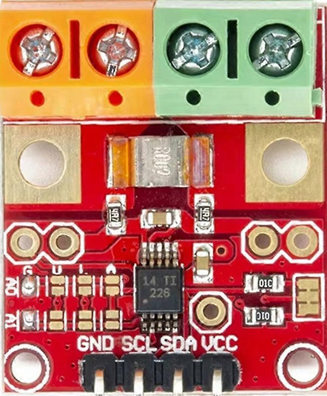
 Design with INA226 in Cirkit Designer
Introduction
The INA226 is a high-side current shunt monitor with an integrated I2C interface, designed for precise measurement of voltage, current, and power. It features a built-in 16-bit analog-to-digital converter (ADC) for high-resolution measurements. The device is capable of operating with a supply voltage range of 2.7V to 5.5V, making it suitable for a wide variety of applications.
Explore Projects Built with INA226
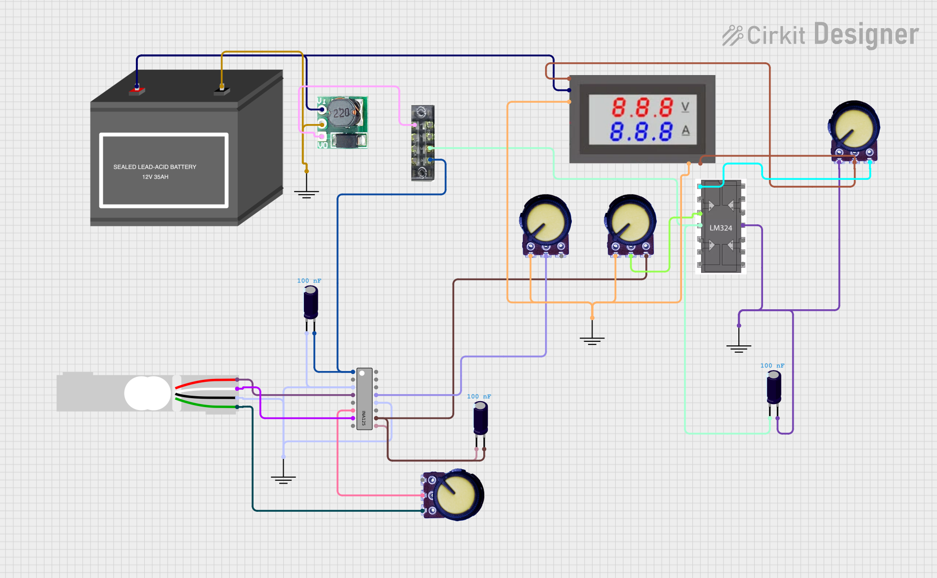 Open Project in Cirkit Designer
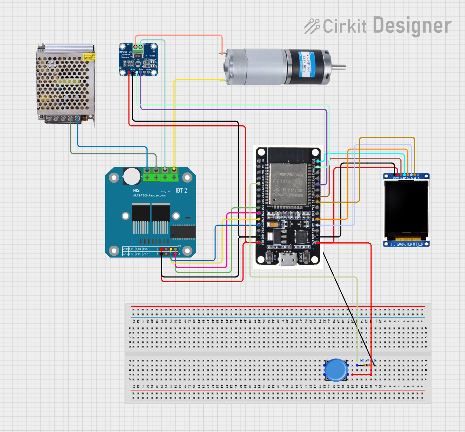 Open Project in Cirkit Designer
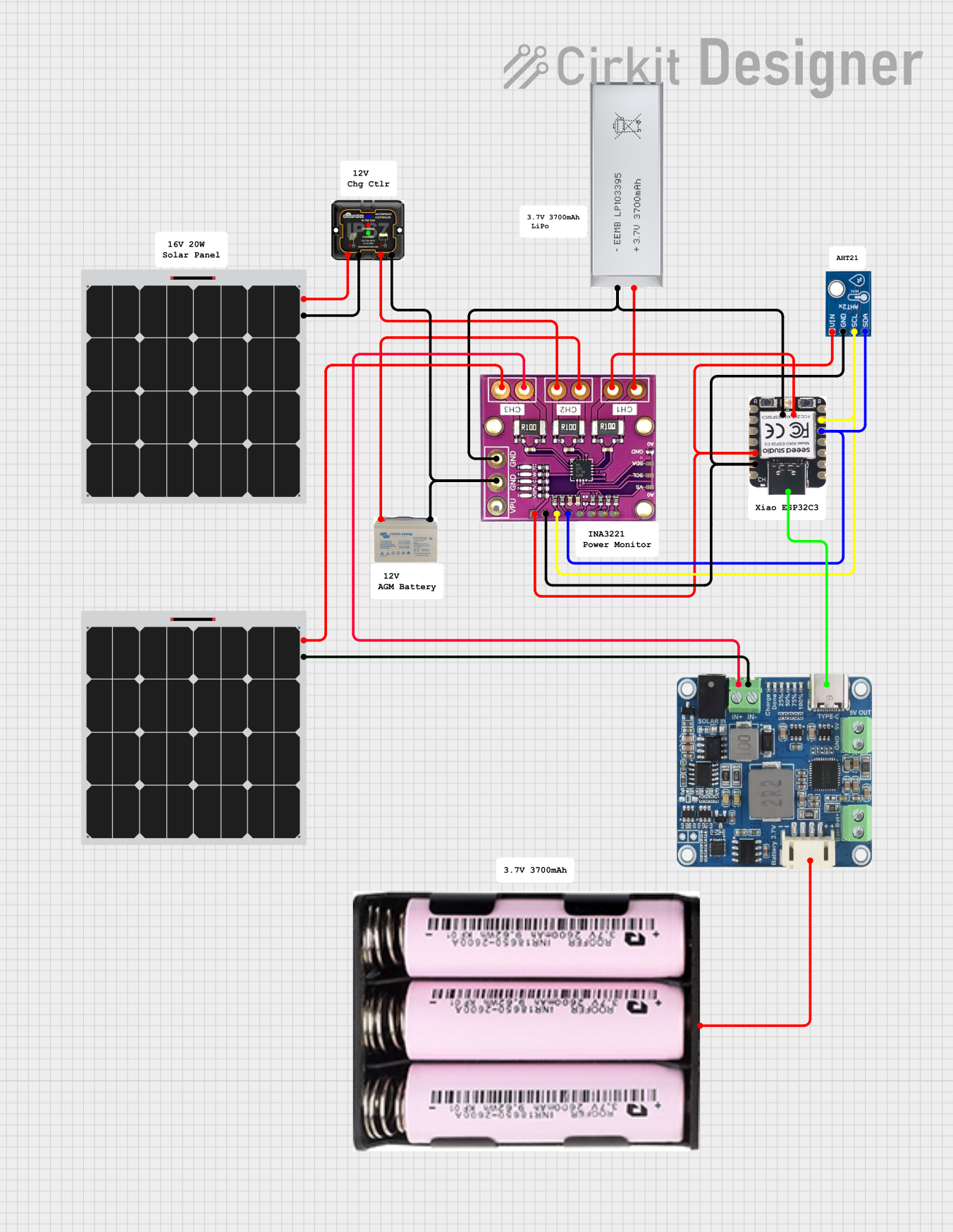 Open Project in Cirkit Designer
 Open Project in Cirkit Designer
Explore Projects Built with INA226
Open Project in Cirkit DesignerOpen Project in Cirkit DesignerOpen Project in Cirkit DesignerOpen Project in Cirkit DesignerCommon Applications and Use Cases
- Power monitoring in embedded systems
- Battery management systems
- DC-DC converter efficiency monitoring
- Industrial automation and control
- IoT devices requiring energy consumption tracking
Technical Specifications
Key Technical Details
| Parameter | Value |
|---|---|
| Supply Voltage (Vcc) | 2.7V to 5.5V |
| Input Voltage Range | 0V to 36V |
| Current Measurement Range | Determined by external shunt resistor |
| ADC Resolution | 16-bit |
| Communication Interface | I2C (up to 1 MHz) |
| Operating Temperature | -40°C to +125°C |
| Power Consumption | 330 µA (typical) |
Pin Configuration and Descriptions
| Pin Number | Pin Name | Description |
|---|---|---|
| 1 | V+ | Positive supply voltage (2.7V to 5.5V) |
| 2 | IN+ | Positive input for current shunt voltage |
| 3 | IN- | Negative input for current shunt voltage |
| 4 | GND | Ground |
| 5 | SCL | I2C clock line |
| 6 | SDA | I2C data line |
| 7 | ALERT/RDY | Alert or Ready output (configurable) |
| 8 | ADDR | I2C address selection pin |
Usage Instructions
How to Use the INA226 in a Circuit
- Power Supply: Connect the V+ pin to a 2.7V to 5.5V power source and the GND pin to ground.
- Shunt Resistor: Place a precision shunt resistor between the IN+ and IN- pins to measure current. The value of the resistor determines the current measurement range.
- Voltage Measurement: Connect the voltage source to be measured to the IN+ pin.
- I2C Communication: Connect the SCL and SDA pins to the corresponding I2C lines of your microcontroller. Use pull-up resistors (typically 4.7kΩ) on these lines.
- Address Configuration: Use the ADDR pin to set the I2C address of the INA226. This allows multiple devices to share the same I2C bus.
- Alert Configuration: Optionally, connect the ALERT/RDY pin to monitor alerts or data readiness.
Important Considerations and Best Practices
- Use a low-tolerance shunt resistor (e.g., 0.1% or better) for accurate current measurements.
- Ensure the voltage across the shunt resistor does not exceed the input voltage range of the INA226.
- Keep the I2C lines as short as possible to minimize noise and ensure reliable communication.
- Configure the INA226 registers appropriately for your application using the I2C interface.
Example Code for Arduino UNO
Below is an example of how to use the INA226 with an Arduino UNO to measure current and voltage:
#include <Wire.h>

// INA226 I2C address (default is 0x40, adjust if ADDR pin is configured differently)
#define INA226_ADDRESS 0x40

// INA226 register addresses
#define CONFIG_REGISTER 0x00
#define SHUNT_VOLTAGE_REGISTER 0x01
#define BUS_VOLTAGE_REGISTER 0x02

void setup() {
  Wire.begin(); // Initialize I2C communication
  Serial.begin(9600); // Initialize serial communication for debugging

  // Configure the INA226 (example configuration)
  Wire.beginTransmission(INA226_ADDRESS);
  Wire.write(CONFIG_REGISTER); // Point to the configuration register
  Wire.write(0x45); // MSB of configuration (example value)
  Wire.write(0x27); // LSB of configuration (example value)
  Wire.endTransmission();
}

void loop() {
  // Read bus voltage
  Wire.beginTransmission(INA226_ADDRESS);
  Wire.write(BUS_VOLTAGE_REGISTER); // Point to the bus voltage register
  Wire.endTransmission();
  Wire.requestFrom(INA226_ADDRESS, 2); // Request 2 bytes of data

  if (Wire.available() == 2) {
    uint16_t busVoltageRaw = (Wire.read() << 8) | Wire.read();
    float busVoltage = busVoltageRaw * 1.25 / 1000; // Convert to volts
    Serial.print("Bus Voltage: ");
    Serial.print(busVoltage);
    Serial.println(" V");
  }

  delay(1000); // Wait 1 second before the next reading
}
Troubleshooting and FAQs
Common Issues and Solutions
No I2C Communication:
- Ensure the SCL and SDA lines are connected correctly and have pull-up resistors.
- Verify the I2C address of the INA226 matches the address in your code.
- Check for loose connections or damaged wires.
Incorrect Voltage or Current Readings:
- Verify the shunt resistor value and ensure it is properly connected.
- Ensure the voltage across the shunt resistor is within the input range of the INA226.
- Double-check the configuration register settings.
Alert Pin Not Functioning:
- Confirm that the ALERT/RDY pin is configured correctly in the INA226 registers.
- Check the microcontroller's GPIO pin configuration.
FAQs
Q: Can the INA226 measure negative currents?
A: No, the INA226 is designed for high-side current sensing and cannot measure negative currents.
Q: What is the maximum current the INA226 can measure?
A: The maximum current depends on the value of the shunt resistor and the maximum input voltage range of the INA226.
Q: Can I use the INA226 with a 3.3V microcontroller?
A: Yes, the INA226 operates with a supply voltage range of 2.7V to 5.5V, making it compatible with 3.3V systems.