How to Use interrupteur 3 poles: Examples, Pinouts, and Specs
Introduction
The Interrupteur 3 Poles (Three-Pole Switch) is an electrical component designed to control multiple circuits simultaneously. It features three separate poles, each capable of connecting or disconnecting an independent circuit. This makes it ideal for applications where multiple circuits need to be controlled in unison, such as in industrial machinery, three-phase motor systems, or complex lighting setups.
Explore Projects Built with interrupteur 3 poles


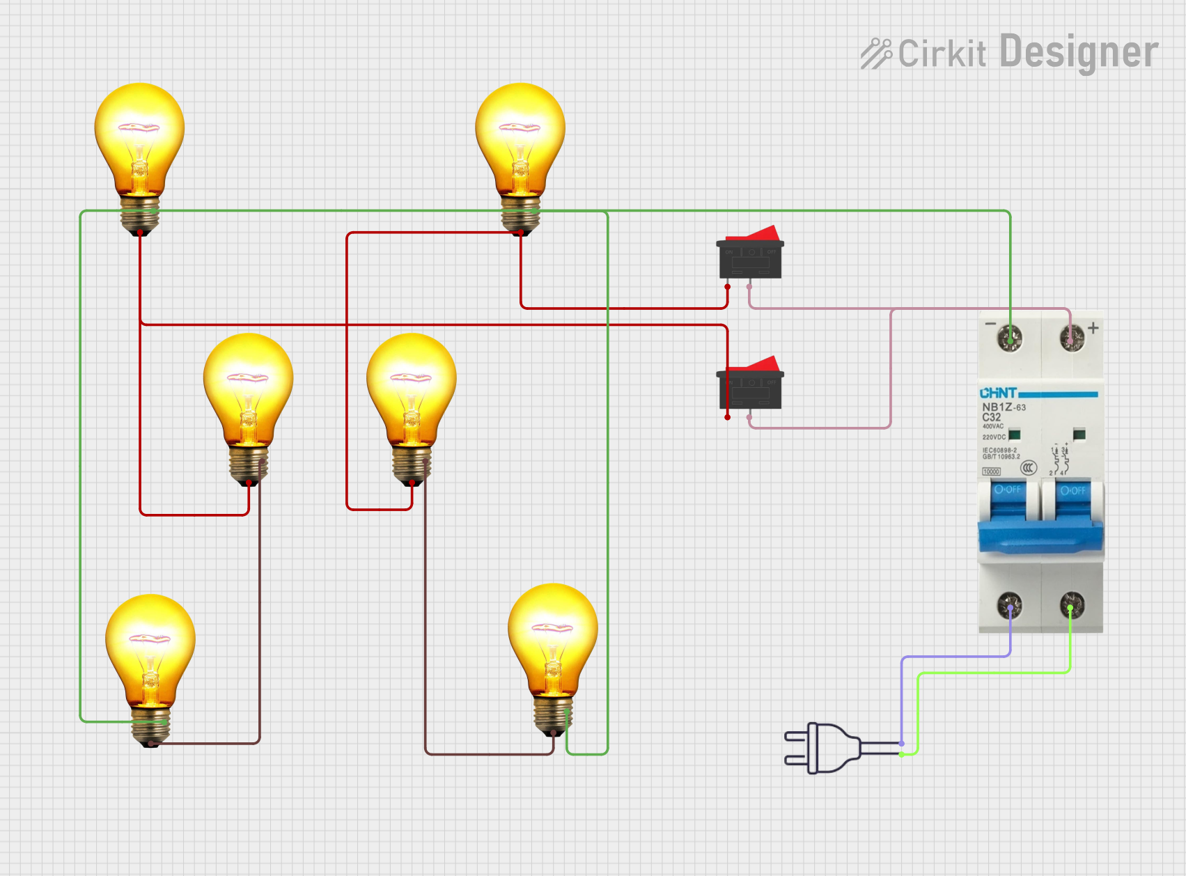
Explore Projects Built with interrupteur 3 poles
Common Applications and Use Cases
- Three-phase motor control: Used to start, stop, or switch three-phase motors.
- Industrial equipment: Controls multiple circuits in machinery or automation systems.
- Lighting systems: Manages multiple lighting circuits in commercial or residential setups.
- Power distribution: Disconnects or isolates multiple circuits for maintenance or safety.
Technical Specifications
The following table outlines the key technical details of the Interrupteur 3 Poles:
| Parameter | Specification |
|---|---|
| Voltage Rating | 250V AC / 440V AC (varies by model) |
| Current Rating | 10A, 16A, 32A (depending on model) |
| Number of Poles | 3 |
| Switching Mechanism | Manual or automatic |
| Contact Type | Normally Open (NO) or Normally Closed (NC) |
| Mounting Type | Panel-mounted or DIN rail-mounted |
| Operating Temperature | -20°C to +70°C |
| Insulation Resistance | ≥ 100 MΩ |
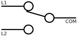
Pin Configuration and Descriptions
The Interrupteur 3 Poles typically has six terminals, with two terminals per pole (input and output). The table below describes the terminal configuration:
| Terminal | Description |
|---|---|
| L1 (Input) | Input terminal for Pole 1 |
| T1 (Output) | Output terminal for Pole 1 |
| L2 (Input) | Input terminal for Pole 2 |
| T2 (Output) | Output terminal for Pole 2 |
| L3 (Input) | Input terminal for Pole 3 |
| T3 (Output) | Output terminal for Pole 3 |
Usage Instructions
How to Use the Component in a Circuit
- Identify the poles: Locate the input (L1, L2, L3) and output (T1, T2, T3) terminals.
- Connect the input terminals: Wire the power source or circuit inputs to the L1, L2, and L3 terminals.
- Connect the output terminals: Wire the devices or circuits to be controlled to the T1, T2, and T3 terminals.
- Secure the switch: Mount the switch securely on a panel or DIN rail, ensuring proper insulation and grounding.
- Test the connections: Verify the connections with a multimeter before powering the circuit.
Important Considerations and Best Practices
- Voltage and current ratings: Ensure the switch's ratings match the circuit requirements to avoid overheating or damage.
- Proper insulation: Use insulated wires and ensure no exposed connections to prevent short circuits or electric shocks.
- Switch type: Choose the appropriate contact type (NO or NC) based on the application.
- Safety precautions: Always disconnect power before wiring or modifying the switch.
Example: Using with an Arduino UNO
While the Interrupteur 3 Poles is not directly compatible with low-voltage microcontrollers like the Arduino UNO, it can be used in conjunction with relays to control high-power circuits. Below is an example of how to use an Arduino UNO to control a three-pole switch via a relay module:
// Example code to control a relay module for a three-pole switch
// Ensure the relay module is rated for the voltage and current of the switch

const int relayPin = 7; // Pin connected to the relay module

void setup() {
  pinMode(relayPin, OUTPUT); // Set the relay pin as an output
  digitalWrite(relayPin, LOW); // Ensure the relay is off initially
}

void loop() {
  // Turn on the relay (activates the three-pole switch)
  digitalWrite(relayPin, HIGH);
  delay(5000); // Keep the switch on for 5 seconds

  // Turn off the relay (deactivates the three-pole switch)
  digitalWrite(relayPin, LOW);
  delay(5000); // Keep the switch off for 5 seconds
}
Troubleshooting and FAQs
Common Issues Users Might Face
Switch does not operate properly:
- Cause: Incorrect wiring or loose connections.
- Solution: Double-check the wiring and ensure all terminals are securely connected.
Overheating of the switch:
- Cause: Exceeding the voltage or current rating.
- Solution: Verify the circuit's power requirements and ensure they are within the switch's specifications.
Arcing or sparking during operation:
- Cause: High inductive loads or worn-out contacts.
- Solution: Use a snubber circuit for inductive loads and replace the switch if contacts are damaged.
Switch fails to isolate circuits:
- Cause: Internal damage or short circuit.
- Solution: Inspect the switch for damage and replace if necessary.
Solutions and Tips for Troubleshooting
- Use a multimeter to test continuity between terminals and verify proper operation.
- Ensure the switch is mounted securely and not exposed to excessive vibration or moisture.
- Regularly inspect the switch for signs of wear, corrosion, or damage.
By following this documentation, users can effectively integrate and maintain the Interrupteur 3 Poles in their electrical systems.