How to Use С2000-КПБ: Examples, Pinouts, and Specs
Introduction
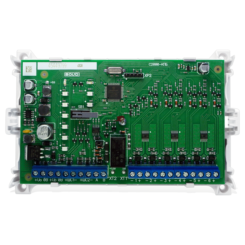
The С2000-КПБ, manufactured by Bolid, is a versatile programmable logic controller (PLC) designed for industrial automation applications. It provides a robust platform for controlling machinery, processes, and systems in a wide range of industries. With its flexible input/output (I/O) options and communication interfaces, the С2000-КПБ is ideal for tasks such as process automation, equipment monitoring, and system integration.
Explore Projects Built with С2000-КПБ


Explore Projects Built with С2000-КПБ
Common Applications and Use Cases
- Industrial process control and automation
- Monitoring and controlling machinery in manufacturing plants
- Integration with SCADA (Supervisory Control and Data Acquisition) systems
- Building automation systems (e.g., HVAC, lighting control)
- Remote monitoring and diagnostics of industrial equipment
Technical Specifications
Key Technical Details
| Parameter | Specification |
|---|---|
| Power Supply | 24V DC ±10% |
| Power Consumption | ≤ 5W |
| Digital Inputs | 8 channels (optically isolated) |
| Digital Outputs | 6 channels (relay-based) |
| Analog Inputs | 2 channels (0-10V or 4-20mA) |
| Communication Interfaces | RS-485, Ethernet |
| Protocols Supported | Modbus RTU, Modbus TCP |
| Operating Temperature Range | -10°C to +50°C |
| Dimensions | 120mm x 90mm x 60mm |
| Mounting | DIN rail |
Pin Configuration and Descriptions
Power and Communication Terminals
| Pin Number | Label | Description |
|---|---|---|
| 1 | +24V | Positive terminal for 24V DC power |
| 2 | GND | Ground terminal |
| 3 | A (RS-485) | RS-485 communication line (A) |
| 4 | B (RS-485) | RS-485 communication line (B) |
| 5 | ETH_TX+ | Ethernet transmit positive |
| 6 | ETH_TX- | Ethernet transmit negative |
| 7 | ETH_RX+ | Ethernet receive positive |
| 8 | ETH_RX- | Ethernet receive negative |
Input/Output Terminals
| Pin Number | Label | Description |
|---|---|---|
| 9-16 | DI1-DI8 | Digital input channels 1 to 8 |
| 17-22 | DO1-DO6 | Digital output channels 1 to 6 |
| 23-24 | AI1, AI2 | Analog input channels 1 and 2 |
Usage Instructions
How to Use the С2000-КПБ in a Circuit
- Power Connection: Connect a 24V DC power supply to the +24V and GND terminals.
- Input Connections:
- For digital inputs, connect sensors or switches to the DI1-DI8 terminals.
- For analog inputs, connect devices providing 0-10V or 4-20mA signals to AI1 and AI2.
- Output Connections:
- Connect actuators, relays, or other devices to the DO1-DO6 terminals.
- Communication Setup:
- Use the RS-485 terminals (A and B) for Modbus RTU communication.
- For Ethernet-based communication, connect the Ethernet cable to the appropriate terminals (ETH_TX+, ETH_TX-, ETH_RX+, ETH_RX-).
- Programming:
- Use the Bolid-provided software to program the PLC according to your application requirements.
- Configure I/O channels, communication settings, and logic sequences.
Important Considerations and Best Practices
- Ensure the power supply voltage is within the specified range (24V DC ±10%).
- Use shielded cables for RS-485 and Ethernet connections to minimize interference.
- Properly terminate the RS-485 bus with a 120-ohm resistor at both ends.
- Avoid exceeding the maximum current ratings for digital outputs to prevent damage.
- Regularly update the firmware to ensure compatibility with the latest features and protocols.
Example Code for Arduino UNO Integration
The С2000-КПБ can communicate with an Arduino UNO via the Modbus RTU protocol over RS-485. Below is an example of how to read a digital input from the PLC using the Arduino Modbus library.
#include <ModbusMaster.h>

// Instantiate ModbusMaster object
ModbusMaster node;

// Define RS-485 communication pins
#define RS485_TX 2  // Arduino TX pin
#define RS485_RX 3  // Arduino RX pin
#define RS485_DE 4  // Driver Enable pin

void setup() {
  // Initialize serial communication for debugging
  Serial.begin(9600);

  // Initialize RS-485 communication
  pinMode(RS485_DE, OUTPUT);
  digitalWrite(RS485_DE, LOW); // Set to receive mode
  Serial1.begin(9600, SERIAL_8N1, RS485_RX, RS485_TX);

  // Configure Modbus communication
  node.begin(1, Serial1); // Set Modbus ID to 1
}

void loop() {
  uint8_t result;
  uint16_t data;

  // Read digital input status from С2000-КПБ (address 0x0000)
  result = node.readDiscreteInputs(0x0000, 1);

  if (result == node.ku8MBSuccess) {
    data = node.getResponseBuffer(0);
    Serial.print("Digital Input Status: ");
    Serial.println(data);
  } else {
    Serial.print("Error: ");
    Serial.println(result);
  }

  delay(1000); // Wait 1 second before next read
}
Notes:
- Use an RS-485 transceiver module (e.g., MAX485) to interface the Arduino with the С2000-КПБ.
- Ensure the Modbus ID and baud rate match the PLC's configuration.
Troubleshooting and FAQs
Common Issues and Solutions
PLC Not Powering On:
- Verify the power supply voltage is within the specified range (24V DC ±10%).
- Check for loose or incorrect wiring at the power terminals.
No Communication via RS-485:
- Ensure the A and B lines are correctly connected.
- Verify the Modbus ID, baud rate, and other communication settings.
- Check for proper termination of the RS-485 bus with a 120-ohm resistor.
Digital Outputs Not Working:
- Confirm the connected load does not exceed the output's current rating.
- Check the program logic to ensure the output is being activated.
Analog Input Readings Are Incorrect:
- Verify the input signal type (0-10V or 4-20mA) matches the PLC configuration.
- Check for proper wiring and ensure the signal source is functioning correctly.
FAQs
Q: Can the С2000-КПБ be used in outdoor environments?
A: The PLC is designed for indoor use. If outdoor installation is required, ensure it is housed in a weatherproof enclosure.
Q: What software is used to program the С2000-КПБ?
A: Bolid provides proprietary software for programming and configuring the PLC. Refer to the manufacturer's website for downloads and documentation.
Q: How many devices can be connected to the RS-485 bus?
A: Up to 32 devices can be connected to the RS-485 bus, including the С2000-КПБ, depending on the network configuration.
Q: Is the С2000-КПБ compatible with third-party SCADA systems?
A: Yes, the PLC supports Modbus RTU and Modbus TCP protocols, making it compatible with most SCADA systems.