How to Use L298: Examples, Pinouts, and Specs
Introduction
The L298 is a robust dual H-bridge motor driver integrated circuit (IC) designed to control the speed and direction of two DC motors simultaneously. It is widely used in robotics, automation, and other electronic applications that require precise motor control. The L298 can handle high current loads and is suitable for driving medium to large motors, making it a popular choice for hobbyists and professionals alike.
Explore Projects Built with L298
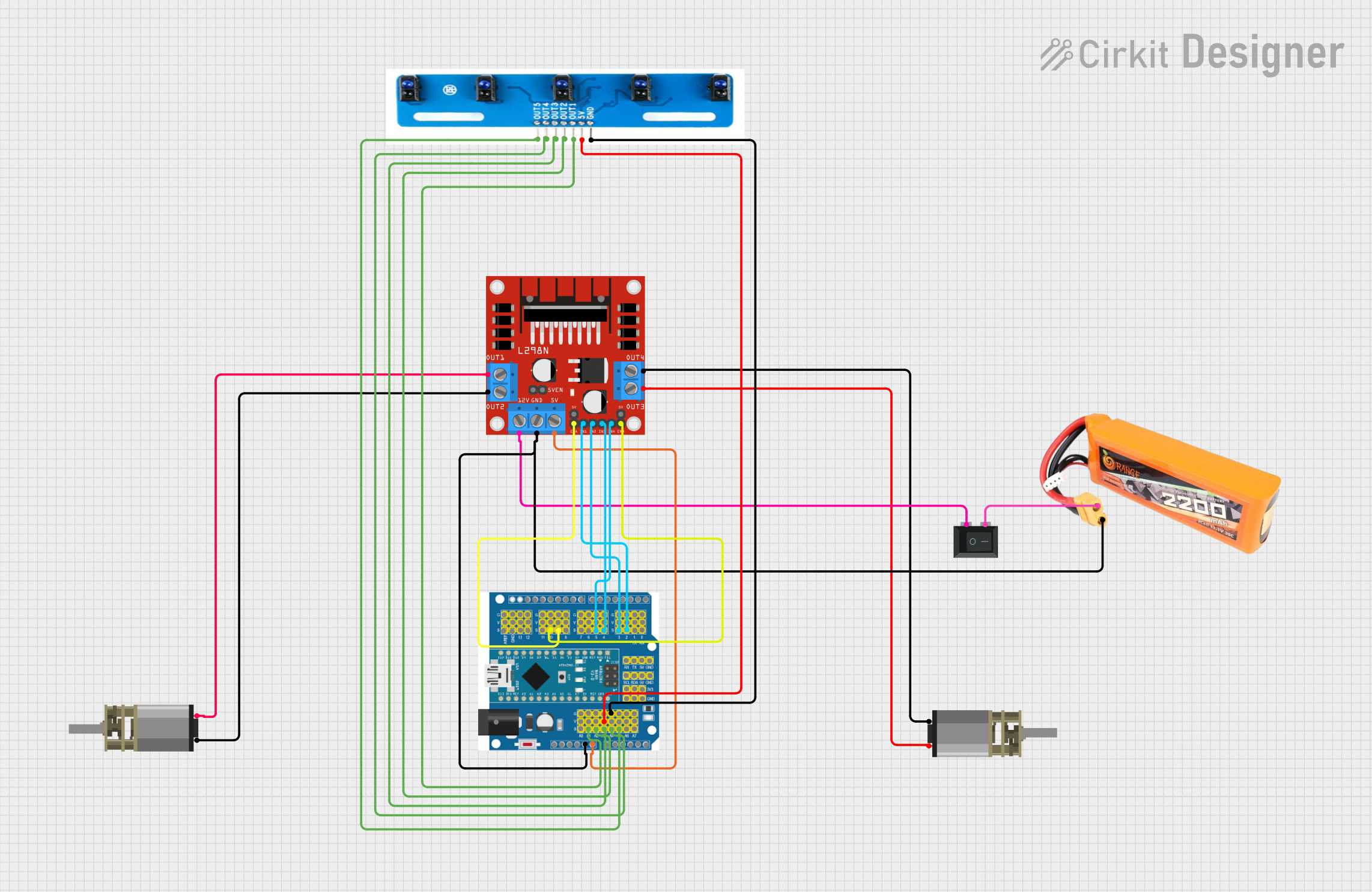

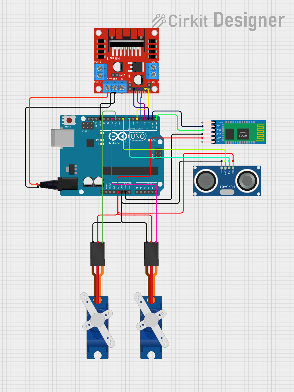
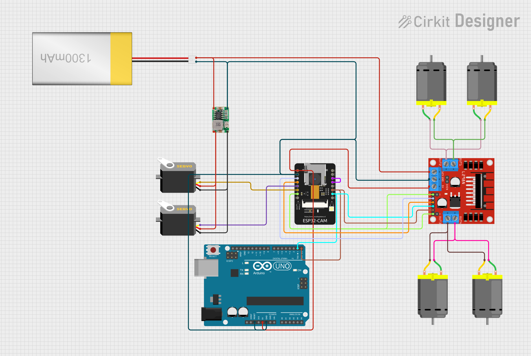
Explore Projects Built with L298
Common Applications and Use Cases
- Robotics: driving wheels or tracks
- CNC machines: controlling stepper motors
- Home automation: operating blinds or curtains
- Educational projects: teaching motor control principles
Technical Specifications
Key Technical Details
- Operating Voltage (Vss): 4.5V to 7V
- Logic Supply Voltage (Vss): Up to 36V
- Peak Output Current (Io): 2A per channel
- Total Power Dissipation (Tcase = 75°C): 25W
Pin Configuration and Descriptions
| Pin Number | Pin Name | Description |
|---|---|---|
| 1 | Vs | Power supply for the motors (up to 46V) |
| 2 | GND | Ground |
| 3 | Vss | Logic supply voltage (5V from Arduino) |
| 4 | Out 1 | Output to motor A (one side of the H-bridge) |
| 5 | Out 2 | Output to motor A (other side of the H-bridge) |
| 6 | EnA | Enable input for motor A (PWM signal for speed control) |
| 7 | In1 | Input 1 for motor A (controls direction) |
| 8 | In2 | Input 2 for motor A (controls direction) |
| ... | ... | ... |
| 15 | In3 | Input 1 for motor B (controls direction) |
| 16 | In4 | Input 2 for motor B (controls direction) |
| 17 | EnB | Enable input for motor B (PWM signal for speed control) |
| 18 | Out 3 | Output to motor B (one side of the H-bridge) |
| 19 | Out 4 | Output to motor B (other side of the H-bridge) |
| 20 | Vs | Power supply for the motors (up to 46V) |
Usage Instructions
How to Use the L298 in a Circuit
- Connect the motor power supply to the Vs pin, and ground to the GND pin.
- Connect the logic supply voltage (5V) from the Arduino to the Vss pin.
- Connect the motor to the Out 1 and Out 2 pins for motor A, and Out 3 and Out 4 for motor B.
- Connect the Arduino digital output pins to In1 and In2 for motor A, and In3 and In4 for motor B.
- Connect the PWM-capable Arduino pins to EnA and EnB for speed control of motor A and B, respectively.
Important Considerations and Best Practices
- Use a separate power supply for the motors to prevent noise and heat affecting the logic circuit.
- Include flyback diodes across the motor terminals to protect the L298 from voltage spikes.
- Use heat sinks if operating near the maximum current rating to dissipate heat.
- Ensure that the power supply can deliver sufficient current for the motors.
Example Arduino Code
#include <Arduino.h>

// Define connections to the L298
const int enA = 9;
const int in1 = 8;
const int in2 = 7;
const int enB = 3;
const int in3 = 4;
const int in4 = 5;

void setup() {
  // Set all the motor control pins to outputs
  pinMode(enA, OUTPUT);
  pinMode(enB, OUTPUT);
  pinMode(in1, OUTPUT);
  pinMode(in2, OUTPUT);
  pinMode(in3, OUTPUT);
  pinMode(in4, OUTPUT);
}

void loop() {
  // Turn on motor A & B
  digitalWrite(in1, HIGH);
  digitalWrite(in2, LOW);
  digitalWrite(in3, HIGH);
  digitalWrite(in4, LOW);

  // Set speed to 200 out of possible range 0-255
  analogWrite(enA, 200);
  analogWrite(enB, 200);

  delay(2000); // Run motors for 2 seconds

  // Now change motor directions
  digitalWrite(in1, LOW);
  digitalWrite(in2, HIGH);
  digitalWrite(in3, LOW);
  digitalWrite(in4, HIGH);

  delay(2000); // Run motors for 2 seconds

  // Now turn off motors
  digitalWrite(in1, LOW);
  digitalWrite(in2, LOW);
  digitalWrite(in3, LOW);
  digitalWrite(in4, LOW);

  delay(2000); // Wait for 2 seconds before next loop
}
Troubleshooting and FAQs
Common Issues Users Might Face
- Motor not running: Check power supply, connections, and ensure that the enable pin is receiving a PWM signal.
- Overheating: Ensure proper heat sinking and that the current does not exceed the maximum rating.
- Inconsistent motor speed: Verify that the PWM signal is stable and that the power supply can handle the load.
Solutions and Tips for Troubleshooting
- Double-check wiring against the pin configuration table.
- Use a multimeter to verify the presence of voltage at the motor outputs.
- Test the L298 with a simple code to isolate the issue from the rest of the circuit.
FAQs
Q: Can the L298 drive stepper motors? A: Yes, the L298 can be used to drive bipolar stepper motors with proper control signals.
Q: What is the maximum current the L298 can handle? A: The L298 can handle up to 2A per channel, but with proper heat sinking.
Q: Can I control the speed of the motors using the L298? A: Yes, by applying a PWM signal to the EnA and EnB pins, you can control the speed of the motors.