
How to Use DRV8833 Dual Motor Driver Carrier: Examples, Pinouts, and Specs
 Design with DRV8833 Dual Motor Driver Carrier in Cirkit Designer
Introduction
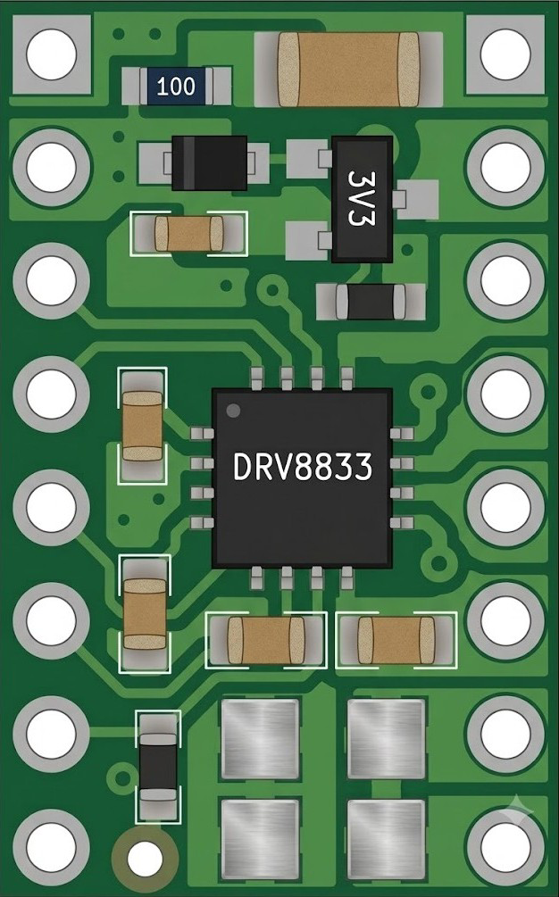
The DRV8833 Dual Motor Driver Carrier, manufactured by Pololu (Part ID: DRV8833), is a compact and efficient motor driver designed to control two DC motors or one stepper motor. It features built-in H-bridge drivers, thermal shutdown, and overcurrent protection, making it a reliable choice for motor control applications. This carrier board simplifies the use of the Texas Instruments DRV8833 motor driver IC by providing easy-to-use breakout pins and additional components for improved performance.
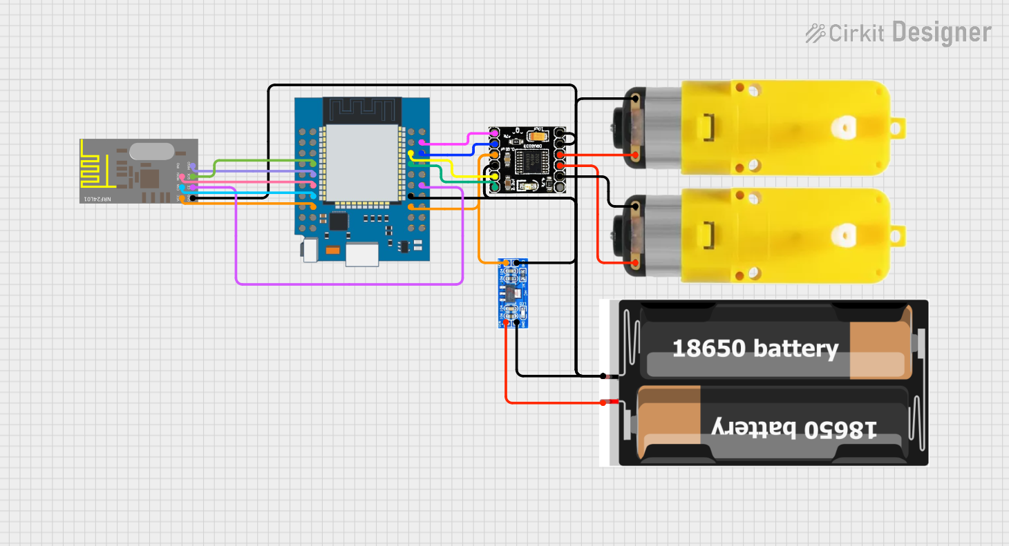
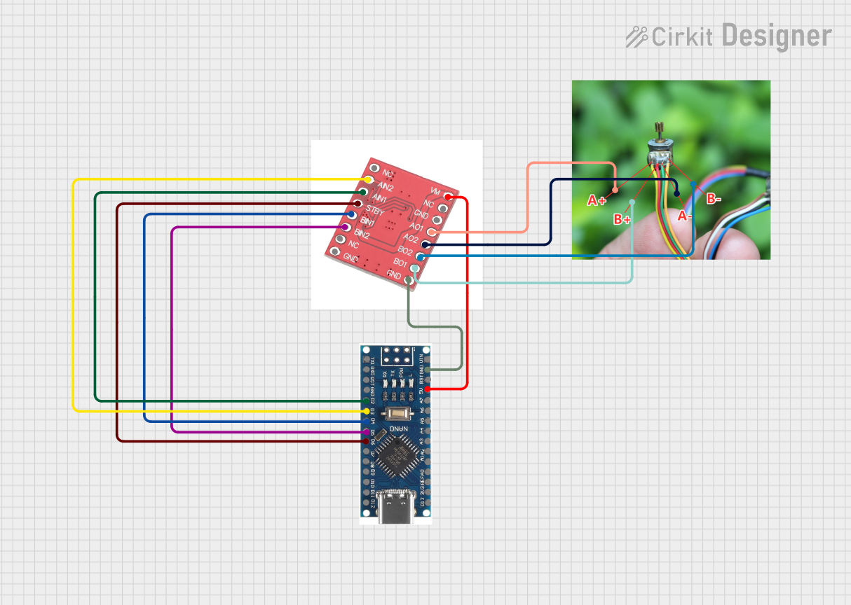
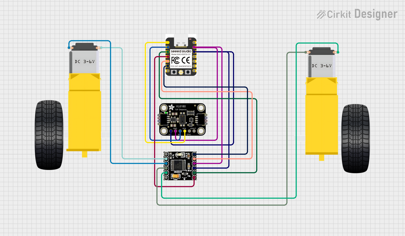
Explore Projects Built with DRV8833 Dual Motor Driver Carrier
 Open Project in Cirkit Designer
 Open Project in Cirkit Designer
 Open Project in Cirkit Designer
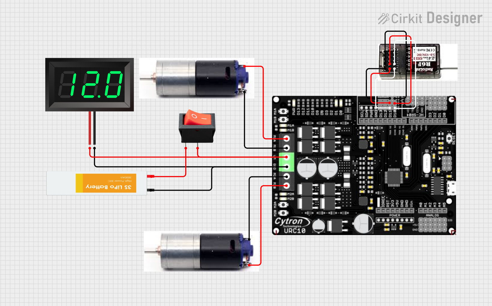 Open Project in Cirkit Designer
Explore Projects Built with DRV8833 Dual Motor Driver Carrier
Open Project in Cirkit DesignerOpen Project in Cirkit DesignerOpen Project in Cirkit DesignerOpen Project in Cirkit DesignerCommon Applications and Use Cases
- Robotics: Driving small to medium-sized DC motors for wheels or actuators.
- Automation: Controlling stepper motors in CNC machines or 3D printers.
- DIY Projects: Motorized toys, conveyor belts, or other motorized mechanisms.
- Educational Projects: Learning motor control with microcontrollers like Arduino or Raspberry Pi.
Technical Specifications
The DRV8833 Dual Motor Driver Carrier has the following key technical details:
| Parameter | Value |
|---|---|
| Operating Voltage | 2.7 V to 10.8 V |
| Continuous Output Current | Up to 1.2 A per channel (with sufficient cooling) |
| Peak Output Current | 2 A per channel (for short durations) |
| Logic Voltage | 2.7 V to 5.5 V |
| Control Interface | PWM (Pulse Width Modulation) and direction control |
| Built-in Protections | Overcurrent, thermal shutdown, undervoltage lockout |
| Dimensions | 0.6" × 0.8" × 0.1" (15 mm × 20 mm × 3 mm) |
| Weight | 0.5 g |
Pin Configuration and Descriptions
The DRV8833 carrier board has 10 pins, as described in the table below:
| Pin | Name | Description |
|---|---|---|
| 1 | VM | Motor power supply (2.7 V to 10.8 V). Connect to the motor power source. |
| 2 | GND | Ground. Connect to the ground of the power supply and control system. |
| 3 | AIN1 | Input 1 for motor A. Controls the direction and speed of motor A (PWM signal). |
| 4 | AIN2 | Input 2 for motor A. Controls the direction and speed of motor A (PWM signal). |
| 5 | BIN1 | Input 1 for motor B. Controls the direction and speed of motor B (PWM signal). |
| 6 | BIN2 | Input 2 for motor B. Controls the direction and speed of motor B (PWM signal). |
| 7 | AO1 | Output 1 for motor A. Connect to one terminal of motor A. |
| 8 | AO2 | Output 2 for motor A. Connect to the other terminal of motor A. |
| 9 | BO1 | Output 1 for motor B. Connect to one terminal of motor B. |
| 10 | BO2 | Output 2 for motor B. Connect to the other terminal of motor B. |
Usage Instructions
How to Use the DRV8833 in a Circuit
Power Connections:
- Connect the motor power supply (2.7 V to 10.8 V) to the
VMpin. - Connect the ground of the power supply and control system to the
GNDpin.
- Connect the motor power supply (2.7 V to 10.8 V) to the
Motor Connections:
- For motor A, connect its terminals to
AO1andAO2. - For motor B, connect its terminals to
BO1andBO2.
- For motor A, connect its terminals to
Control Connections:
- Use the
AIN1andAIN2pins to control motor A. - Use the
BIN1andBIN2pins to control motor B. - Apply PWM signals to these pins to control motor speed and direction.
- Use the
Logic Voltage:
- Ensure the control signals are within the logic voltage range (2.7 V to 5.5 V).
Important Considerations and Best Practices
- Heat Dissipation: The DRV8833 can handle up to 1.2 A per channel continuously, but proper cooling (e.g., a heat sink or adequate ventilation) is required to prevent overheating.
- Power Supply: Ensure the motor power supply voltage matches the motor's requirements and stays within the DRV8833's operating range.
- Protection Features: The built-in protections (overcurrent, thermal shutdown) help prevent damage, but avoid prolonged operation near the current or voltage limits.
Example Code for Arduino UNO
Below is an example of how to control two DC motors using the DRV8833 with an Arduino UNO:
// Define motor control pins
const int AIN1 = 3; // Motor A input 1 (PWM)
const int AIN2 = 4; // Motor A input 2
const int BIN1 = 5; // Motor B input 1 (PWM)
const int BIN2 = 6; // Motor B input 2

void setup() {
  // Set motor control pins as outputs
  pinMode(AIN1, OUTPUT);
  pinMode(AIN2, OUTPUT);
  pinMode(BIN1, OUTPUT);
  pinMode(BIN2, OUTPUT);
}

void loop() {
  // Example: Rotate motor A forward at 50% speed
  analogWrite(AIN1, 128); // 50% duty cycle
  digitalWrite(AIN2, LOW);

  // Example: Rotate motor B backward at 75% speed
  digitalWrite(BIN1, LOW);
  analogWrite(BIN2, 192); // 75% duty cycle

  delay(2000); // Run motors for 2 seconds

  // Stop both motors
  digitalWrite(AIN1, LOW);
  digitalWrite(AIN2, LOW);
  digitalWrite(BIN1, LOW);
  digitalWrite(BIN2, LOW);

  delay(2000); // Wait for 2 seconds before repeating
}
Troubleshooting and FAQs
Common Issues and Solutions
Motors Not Spinning:
- Verify all connections, especially the power supply and motor terminals.
- Ensure the control signals (PWM and direction) are correctly configured.
Overheating:
- Check if the current draw exceeds 1.2 A per channel.
- Improve cooling by adding a heat sink or increasing ventilation.
Erratic Motor Behavior:
- Ensure the power supply voltage is stable and within the specified range.
- Check for loose or intermittent connections.
No Response from the Driver:
- Confirm that the logic voltage (control signals) is within 2.7 V to 5.5 V.
- Test the motor driver with a different motor or microcontroller to isolate the issue.
FAQs
Q: Can the DRV8833 drive stepper motors?
A: Yes, the DRV8833 can control a single bipolar stepper motor by using both motor channels. You will need to implement stepper motor control logic in your code.
Q: What happens if the current exceeds 2 A?
A: The DRV8833 has built-in overcurrent protection that will temporarily disable the outputs to prevent damage. Reduce the load or improve cooling to avoid triggering this protection.
Q: Can I use a 12 V power supply?
A: No, the maximum motor power supply voltage is 10.8 V. Using a higher voltage may damage the driver.
Q: Is it compatible with 3.3 V logic?
A: Yes, the DRV8833 supports logic voltages as low as 2.7 V, making it compatible with 3.3 V systems like the Raspberry Pi.