How to Use Buzzer: Examples, Pinouts, and Specs
Introduction
A buzzer is an audio signaling device that produces sound when an electric current passes through it. Manufactured by Anand with the part ID Buzzer-1, this component is widely used in various applications where audible alerts or notifications are required. It is compact, easy to use, and highly reliable, making it a popular choice for both hobbyist and professional projects.
Explore Projects Built with Buzzer

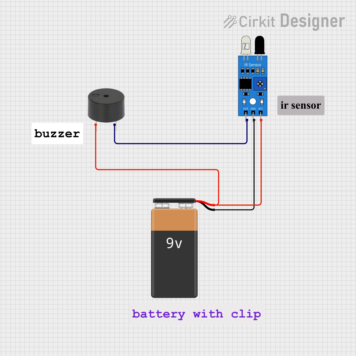
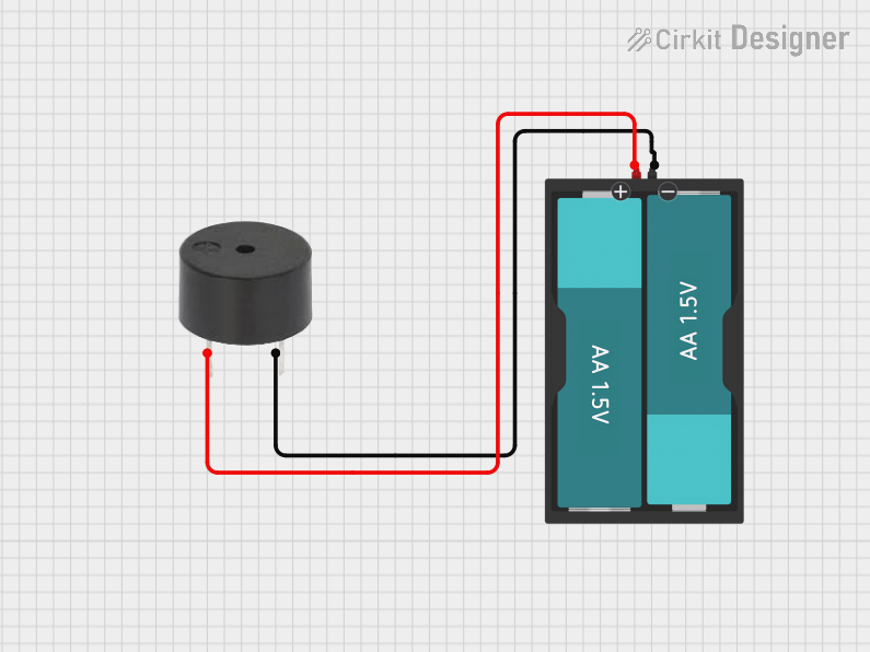

Explore Projects Built with Buzzer
Common Applications and Use Cases
- Alarm systems (e.g., burglar alarms, fire alarms)
- Timers and reminders
- Notification systems in appliances (e.g., microwave ovens, washing machines)
- Feedback systems in electronic devices
- Educational and DIY electronics projects
Technical Specifications
The Anand Buzzer-1 is a simple yet versatile component. Below are its key technical details:
General Specifications
| Parameter | Value |
|---|---|
| Operating Voltage | 3V to 12V DC |
| Rated Voltage | 5V DC |
| Current Consumption | ≤ 30 mA |
| Sound Output | 85 dB at 10 cm (typical) |
| Frequency Range | 2 kHz to 4 kHz |
| Operating Temperature | -20°C to +60°C |
| Dimensions | 12 mm (diameter) x 8 mm |
Pin Configuration
The Buzzer-1 has two pins for electrical connections. The table below describes the pin configuration:
| Pin Number | Name | Description |
|---|---|---|
| 1 | Positive (+) | Connect to the positive terminal of the power supply or control signal. |
| 2 | Negative (-) | Connect to the ground (GND) of the circuit. |
Usage Instructions
Using the Buzzer-1 in a circuit is straightforward. Follow the steps below to integrate it into your project:
Basic Circuit Connection
- Power Supply: Connect the positive pin of the buzzer to the positive terminal of the power supply (e.g., 5V DC).
- Ground Connection: Connect the negative pin of the buzzer to the ground (GND) of the circuit.
- Control Signal (Optional): If you want to control the buzzer using a microcontroller (e.g., Arduino), connect the positive pin to a digital output pin of the microcontroller through a current-limiting resistor (e.g., 220Ω).
Example: Connecting to an Arduino UNO
Below is an example of how to connect and control the Buzzer-1 using an Arduino UNO:
Circuit Diagram
- Connect the positive pin of the buzzer to Arduino digital pin 8.
- Connect the negative pin of the buzzer to the Arduino GND.
Arduino Code
// Buzzer Control Example
// This code demonstrates how to turn the buzzer on and off using an Arduino UNO.

#define BUZZER_PIN 8  // Define the pin connected to the buzzer

void setup() {
  pinMode(BUZZER_PIN, OUTPUT);  // Set the buzzer pin as an output
}

void loop() {
  digitalWrite(BUZZER_PIN, HIGH);  // Turn the buzzer ON
  delay(1000);                     // Wait for 1 second
  digitalWrite(BUZZER_PIN, LOW);   // Turn the buzzer OFF
  delay(1000);                     // Wait for 1 second
}
Important Considerations and Best Practices
- Voltage Range: Ensure the operating voltage is within the specified range (3V to 12V DC). Exceeding this range may damage the buzzer.
- Current Limiting: Use a current-limiting resistor if the buzzer is connected to a microcontroller to prevent excessive current draw.
- Polarity: Always connect the positive and negative pins correctly. Reversing the polarity may result in malfunction or damage.
- Mounting: Secure the buzzer in place to prevent vibrations from affecting its performance.
Troubleshooting and FAQs
Common Issues and Solutions
No Sound from the Buzzer:
- Check the power supply voltage and ensure it is within the operating range.
- Verify the polarity of the connections (positive and negative pins).
- Ensure the control signal (if used) is correctly configured in the circuit.
Buzzer Produces Weak or Distorted Sound:
- Confirm that the power supply provides sufficient current (≥ 30 mA).
- Check for loose or poor connections in the circuit.
- Ensure the buzzer is not exposed to extreme temperatures beyond its operating range.
Buzzer Overheats:
- Verify that the operating voltage does not exceed the rated voltage (5V DC).
- Use a current-limiting resistor if necessary.
FAQs
Q1: Can I use the buzzer with an AC power supply?
A1: No, the Buzzer-1 is designed for DC power only. Using an AC power supply may damage the component.
Q2: How can I make the buzzer produce different tones?
A2: You can generate different tones by using a microcontroller (e.g., Arduino) to send a PWM (Pulse Width Modulation) signal to the buzzer. Adjust the frequency of the PWM signal to change the tone.
Q3: Is the buzzer waterproof?
A3: No, the Buzzer-1 is not waterproof. Avoid exposing it to moisture or water.
Q4: Can I use the buzzer in battery-powered projects?
A4: Yes, the buzzer is suitable for battery-powered projects as long as the voltage is within the operating range.
By following this documentation, you can effectively integrate the Anand Buzzer-1 into your projects and troubleshoot any issues that may arise.