How to Use YJTF08A-E Relay: Examples, Pinouts, and Specs
Introduction
The YJTF08A-E Relay is an electromechanical switching device designed for a wide range of applications. It features a compact design and is capable of handling various loads, making it suitable for both low-power and high-power switching tasks. This relay operates electrically to open or close circuits, providing isolation and control in electronic systems. Its versatility and reliability make it a popular choice in industrial automation, home appliances, automotive systems, and more.
Explore Projects Built with YJTF08A-E Relay


Explore Projects Built with YJTF08A-E Relay
Common Applications:
- Industrial automation systems
- Home appliances (e.g., washing machines, HVAC systems)
- Automotive electronics
- Power distribution and control systems
- Microcontroller-based projects (e.g., Arduino, Raspberry Pi)
Technical Specifications
Below are the key technical details of the YJTF08A-E Relay:
| Parameter | Specification |
|---|---|
| Coil Voltage | 5V DC, 12V DC, or 24V DC (varies by model) |
| Contact Configuration | SPDT (Single Pole Double Throw) |
| Contact Rating | 10A at 250V AC / 10A at 30V DC |
| Coil Resistance | 70Ω (5V model), 290Ω (12V model), 1150Ω (24V model) |
| Operate Time | ≤10 ms |
| Release Time | ≤5 ms |
| Insulation Resistance | ≥100 MΩ at 500V DC |
| Dielectric Strength | 1500V AC (coil to contacts) |
| Mechanical Life | 10 million operations |
| Electrical Life | 100,000 operations |
| Dimensions | 28mm x 12.5mm x 15mm |
| Weight | Approximately 10g |
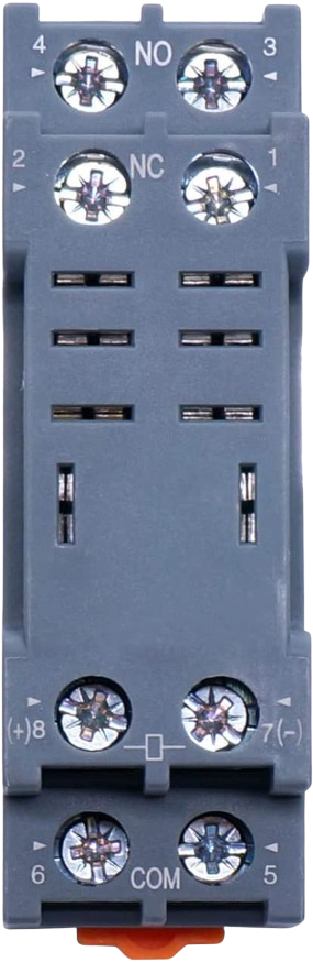
Pin Configuration and Descriptions
The YJTF08A-E Relay typically has 5 pins, as described in the table below:
| Pin Number | Name | Description |
|---|---|---|
| 1 | Coil (+) | Positive terminal of the relay coil |
| 2 | Coil (-) | Negative terminal of the relay coil |
| 3 | Common (COM) | Common terminal for the switching contacts |
| 4 | Normally Open (NO) | Open circuit when the relay is inactive; closes when activated |
| 5 | Normally Closed (NC) | Closed circuit when the relay is inactive; opens when activated |
Usage Instructions
How to Use the YJTF08A-E Relay in a Circuit
- Power the Coil: Connect the relay's coil pins (1 and 2) to a DC power source matching the relay's rated coil voltage (e.g., 5V, 12V, or 24V).
- Control the Load: Connect the load to the Common (COM) pin (3) and either the Normally Open (NO) pin (4) or Normally Closed (NC) pin (5), depending on the desired behavior:
- Use the NO pin if the load should be powered only when the relay is activated.
- Use the NC pin if the load should be powered when the relay is inactive.
- Switching: Apply a control signal to the relay coil to activate or deactivate the relay, thereby switching the load.
Important Considerations and Best Practices
- Diode Protection: Always connect a flyback diode across the relay coil to protect the driving circuit from voltage spikes caused by the coil's inductance.
- Power Ratings: Ensure the load's voltage and current do not exceed the relay's contact rating (10A at 250V AC or 10A at 30V DC).
- Isolation: Use optocouplers or transistors to isolate the relay from sensitive control circuits, especially when interfacing with microcontrollers.
- Mounting: Secure the relay properly to avoid mechanical vibrations that could affect its operation.
Example: Connecting the YJTF08A-E Relay to an Arduino UNO
Below is an example of how to control the YJTF08A-E Relay using an Arduino UNO:
Circuit Connections:
- Connect the relay's Coil (+) pin to a digital output pin on the Arduino (e.g., pin 7) through a transistor.
- Connect the relay's Coil (-) pin to the Arduino's GND.
- Add a flyback diode (e.g., 1N4007) across the relay coil.
- Connect the load to the relay's COM and NO pins.
Arduino Code:
// Define the relay pin
const int relayPin = 7;

void setup() {
  pinMode(relayPin, OUTPUT); // Set the relay pin as an output
  digitalWrite(relayPin, LOW); // Ensure the relay is off initially
}

void loop() {
  digitalWrite(relayPin, HIGH); // Activate the relay
  delay(1000); // Keep the relay on for 1 second
  digitalWrite(relayPin, LOW); // Deactivate the relay
  delay(1000); // Keep the relay off for 1 second
}
Troubleshooting and FAQs
Common Issues and Solutions
Relay Not Activating:
- Cause: Insufficient voltage or current to the relay coil.
- Solution: Verify the power supply voltage matches the relay's rated coil voltage. Check the driving circuit for proper operation.
Load Not Switching:
- Cause: Incorrect wiring of the load to the relay contacts.
- Solution: Double-check the connections to the COM, NO, and NC pins.
Voltage Spikes Damaging Circuit:
- Cause: Lack of a flyback diode across the relay coil.
- Solution: Install a flyback diode (e.g., 1N4007) across the coil terminals.
Relay Buzzing or Chattering:
- Cause: Insufficient or unstable power supply to the coil.
- Solution: Ensure the power supply is stable and capable of providing the required current.
FAQs
Q: Can the YJTF08A-E Relay handle AC and DC loads?
A: Yes, the relay can handle both AC (up to 250V) and DC (up to 30V) loads, provided the current does not exceed 10A.
Q: Is the relay suitable for direct connection to a microcontroller?
A: No, the relay coil typically requires more current than a microcontroller can provide. Use a transistor or relay driver circuit for interfacing.
Q: What is the purpose of the NC pin?
A: The NC (Normally Closed) pin allows the load to remain powered when the relay is inactive. It opens the circuit when the relay is activated.