Cirkit Designer Logo
Cirkit Designer
Your all-in-one circuit design IDE
Home / 
Component Documentation

How to Use AS7343: Examples, Pinouts, and Specs

Image of AS7343
Cirkit Designer LogoDesign with AS7343 in Cirkit Designer

Introduction

The AS7343 is a highly versatile spectral sensor designed to measure light intensity across multiple wavelengths. It features a 6-channel photodiode array, enabling precise color sensing and spectral analysis. This component is widely used in applications such as environmental monitoring, color matching, industrial process control, and portable spectroscopy. Its compact design and high sensitivity make it ideal for integration into IoT devices, smart lighting systems, and consumer electronics.

Explore Projects Built with AS7343

Use Cirkit Designer to design, explore, and prototype these projects online. Some projects support real-time simulation. Click "Open Project" to start designing instantly!
Battery-Powered Emergency Alert System with NUCLEO-F072RB, SIM800L, and GPS NEO 6M
Image of women safety: A project utilizing AS7343 in a practical application
This circuit is an emergency alert system that uses a NUCLEO-F072RB microcontroller to send SMS alerts and make calls via a SIM800L GSM module, while obtaining location data from a GPS NEO 6M module. The system is powered by a Li-ion battery and includes a TP4056 module for battery charging and protection, with a rocker switch to control power to the microcontroller.
Cirkit Designer LogoOpen Project in Cirkit Designer
Satellite-Based Timing and Navigation System with SDR and Atomic Clock Synchronization
Image of GPS 시스템 측정 구성도_Confirm: A project utilizing AS7343 in a practical application
This circuit appears to be a complex system involving power supply management, GPS and timing synchronization, and data communication. It includes a SI-TEX G1 Satellite Compass for GPS data, an XHTF1021 Atomic Rubidium Clock for precise timing, and Ettus USRP B200 units for software-defined radio communication. Power is supplied through various SMPS units and distributed via terminal blocks and DC jacks. Data communication is facilitated by Beelink MINI S12 N95 computers, RS232 splitters, and a 1000BASE-T Media Converter for network connectivity. RF Directional Couplers are used to interface antennas with the USRP units, and the entire system is likely contained within cases for protection and organization.
Cirkit Designer LogoOpen Project in Cirkit Designer
Logic Gate Circuit with 7408 AND and 7432 OR ICs
Image of gate: A project utilizing AS7343 in a practical application
This circuit includes a 7408 AND gate IC and a 7432 OR gate IC, both powered by a common VCC and GND connection. The circuit is designed to perform basic logical operations, combining AND and OR gates for digital signal processing.
Cirkit Designer LogoOpen Project in Cirkit Designer
Arduino Mega 2560 Based Security System with Fingerprint Authentication and SMS Alerts
Image of Door security system: A project utilizing AS7343 in a practical application
This circuit features an Arduino Mega 2560 microcontroller interfaced with a SIM800L GSM module, two fingerprint scanners, an I2C LCD display, an IR sensor, and a piezo buzzer. Power management is handled by a PowerBoost 1000 Basic Pad USB, a TP4056 charging module, and a Li-ion 18650 battery, with an option to use a Mini AC-DC 110V-230V to 5V 700mA module for direct power supply. The primary functionality appears to be a security system with GSM communication capabilities, biometric access control, and visual/audible feedback.
Cirkit Designer LogoOpen Project in Cirkit Designer

Explore Projects Built with AS7343

Use Cirkit Designer to design, explore, and prototype these projects online. Some projects support real-time simulation. Click "Open Project" to start designing instantly!
Image of women safety: A project utilizing AS7343 in a practical application
Battery-Powered Emergency Alert System with NUCLEO-F072RB, SIM800L, and GPS NEO 6M
This circuit is an emergency alert system that uses a NUCLEO-F072RB microcontroller to send SMS alerts and make calls via a SIM800L GSM module, while obtaining location data from a GPS NEO 6M module. The system is powered by a Li-ion battery and includes a TP4056 module for battery charging and protection, with a rocker switch to control power to the microcontroller.
Cirkit Designer LogoOpen Project in Cirkit Designer
Image of GPS 시스템 측정 구성도_Confirm: A project utilizing AS7343 in a practical application
Satellite-Based Timing and Navigation System with SDR and Atomic Clock Synchronization
This circuit appears to be a complex system involving power supply management, GPS and timing synchronization, and data communication. It includes a SI-TEX G1 Satellite Compass for GPS data, an XHTF1021 Atomic Rubidium Clock for precise timing, and Ettus USRP B200 units for software-defined radio communication. Power is supplied through various SMPS units and distributed via terminal blocks and DC jacks. Data communication is facilitated by Beelink MINI S12 N95 computers, RS232 splitters, and a 1000BASE-T Media Converter for network connectivity. RF Directional Couplers are used to interface antennas with the USRP units, and the entire system is likely contained within cases for protection and organization.
Cirkit Designer LogoOpen Project in Cirkit Designer
Image of gate: A project utilizing AS7343 in a practical application
Logic Gate Circuit with 7408 AND and 7432 OR ICs
This circuit includes a 7408 AND gate IC and a 7432 OR gate IC, both powered by a common VCC and GND connection. The circuit is designed to perform basic logical operations, combining AND and OR gates for digital signal processing.
Cirkit Designer LogoOpen Project in Cirkit Designer
Image of Door security system: A project utilizing AS7343 in a practical application
Arduino Mega 2560 Based Security System with Fingerprint Authentication and SMS Alerts
This circuit features an Arduino Mega 2560 microcontroller interfaced with a SIM800L GSM module, two fingerprint scanners, an I2C LCD display, an IR sensor, and a piezo buzzer. Power management is handled by a PowerBoost 1000 Basic Pad USB, a TP4056 charging module, and a Li-ion 18650 battery, with an option to use a Mini AC-DC 110V-230V to 5V 700mA module for direct power supply. The primary functionality appears to be a security system with GSM communication capabilities, biometric access control, and visual/audible feedback.
Cirkit Designer LogoOpen Project in Cirkit Designer

Technical Specifications

The AS7343 offers robust performance with the following key specifications:

Key Technical Details

  • Operating Voltage: 1.8V (I/O) and 3.3V (core)
  • Spectral Channels: 6 photodiodes covering visible and near-infrared wavelengths
  • Communication Interface: I²C (up to 1 MHz)
  • Spectral Range: 350 nm to 1000 nm
  • Measurement Resolution: 16-bit ADC
  • Operating Temperature: -40°C to +85°C
  • Package: 2.0 mm x 2.0 mm x 0.75 mm, 8-pin LGA

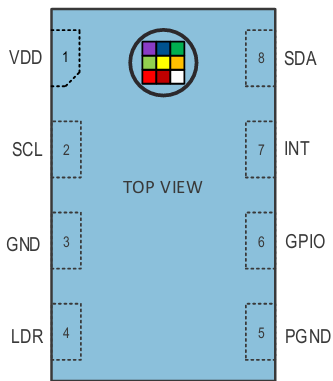
Pin Configuration and Descriptions

The AS7343 has an 8-pin layout, as described in the table below:

Pin Number Pin Name Description
1 VDD Power supply (3.3V)
2 GND Ground
3 SDA I²C data line
4 SCL I²C clock line
5 INT Interrupt output (active low)
6 GPIO1 General-purpose I/O
7 GPIO2 General-purpose I/O
8 NC Not connected (leave floating)

Usage Instructions

How to Use the AS7343 in a Circuit

  1. Power Supply: Connect the VDD pin to a 3.3V power source and the GND pin to ground.
  2. I²C Communication: Connect the SDA and SCL pins to the corresponding I²C pins on your microcontroller. Use pull-up resistors (typically 4.7 kΩ) on both lines.
  3. Interrupt Pin: Optionally, connect the INT pin to a GPIO pin on your microcontroller to handle interrupts.
  4. GPIO Pins: The GPIO1 and GPIO2 pins can be configured for additional functionality, such as triggering external events.

Important Considerations and Best Practices

  • I²C Address: The default I²C address of the AS7343 is 0x39. Ensure no address conflicts if multiple devices are on the same bus.
  • Spectral Calibration: For accurate measurements, calibrate the sensor based on your specific application and light source.
  • Avoid Saturation: Ensure the light intensity does not exceed the sensor's maximum range to avoid saturation.
  • Placement: Minimize external light interference by using an optical enclosure or lens.

Example Code for Arduino UNO

Below is an example of how to interface the AS7343 with an Arduino UNO using the I²C protocol:

#include <Wire.h>

// AS7343 I²C address
#define AS7343_ADDR 0x39

void setup() {
  Wire.begin(); // Initialize I²C communication
  Serial.begin(9600); // Initialize serial communication for debugging

  // Configure AS7343
  Wire.beginTransmission(AS7343_ADDR);
  Wire.write(0x80); // Select control register
  Wire.write(0x03); // Enable the sensor
  Wire.endTransmission();

  Serial.println("AS7343 initialized.");
}

void loop() {
  // Request data from AS7343
  Wire.beginTransmission(AS7343_ADDR);
  Wire.write(0x94); // Select data register
  Wire.endTransmission();

  Wire.requestFrom(AS7343_ADDR, 2); // Request 2 bytes of data
  if (Wire.available() == 2) {
    uint16_t lightData = Wire.read() | (Wire.read() << 8); // Combine bytes
    Serial.print("Light Intensity: ");
    Serial.println(lightData);
  }

  delay(1000); // Wait 1 second before next reading
}

Troubleshooting and FAQs

Common Issues

  1. No Data from Sensor:

    • Cause: Incorrect I²C wiring or address mismatch.
    • Solution: Verify the SDA and SCL connections and ensure the I²C address matches 0x39.
  2. Inconsistent Readings:

    • Cause: External light interference or improper calibration.
    • Solution: Use an optical enclosure and perform spectral calibration.
  3. Sensor Not Responding:

    • Cause: Insufficient power supply or incorrect initialization.
    • Solution: Ensure the VDD pin is supplied with 3.3V and check the initialization code.

FAQs

  • Can the AS7343 measure UV light?

    • No, the AS7343 is designed for visible and near-infrared light (350 nm to 1000 nm).
  • What is the maximum I²C speed supported?

    • The AS7343 supports I²C speeds up to 1 MHz.
  • Is the AS7343 compatible with 5V logic?

    • No, the AS7343 operates at 1.8V for I/O. Use a level shifter if interfacing with 5V logic.

By following this documentation, you can effectively integrate the AS7343 into your projects for accurate spectral sensing and analysis.