
How to Use ESP32 - CAM: Examples, Pinouts, and Specs
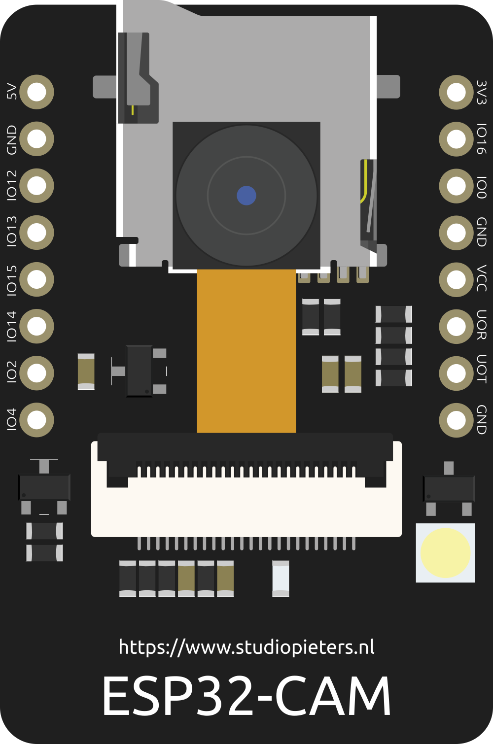
 Design with ESP32 - CAM in Cirkit Designer
Introduction
The ESP32-CAM is a low-cost, low-power system on a chip (SoC) that integrates Wi-Fi and Bluetooth capabilities, along with a camera interface for image and video capture. It is based on the ESP32 microcontroller and is widely used in IoT applications, smart home devices, surveillance systems, and projects requiring wireless connectivity and image processing. Its compact size and powerful features make it an excellent choice for developers and hobbyists alike.
Explore Projects Built with ESP32 - CAM
 Open Project in Cirkit Designer
 Open Project in Cirkit Designer
 Open Project in Cirkit Designer
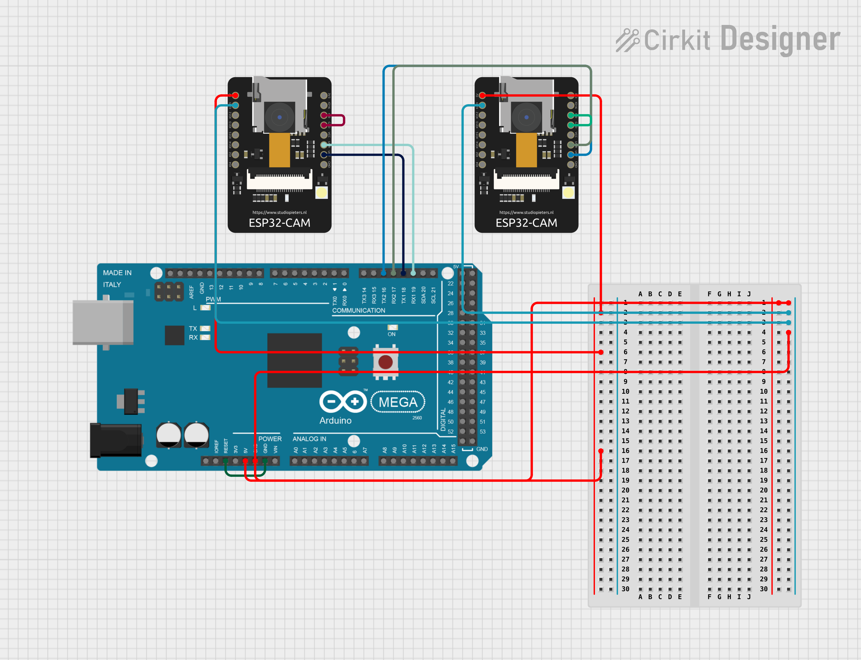 Open Project in Cirkit Designer
Explore Projects Built with ESP32 - CAM
Open Project in Cirkit DesignerOpen Project in Cirkit DesignerOpen Project in Cirkit DesignerOpen Project in Cirkit DesignerCommon Applications
- Wireless surveillance cameras
- Smart doorbells and home automation systems
- IoT projects requiring image or video capture
- Face recognition and object detection systems
- Remote monitoring and control systems
Technical Specifications
Key Technical Details
| Specification | Value |
|---|---|
| Microcontroller | ESP32 Dual-Core Processor |
| Wireless Connectivity | Wi-Fi 802.11 b/g/n, Bluetooth 4.2 |
| Camera Interface | OV2640 (default camera module) |
| Flash Memory | 4 MB (PSRAM) |
| Operating Voltage | 3.3V |
| Input Voltage Range | 5V (via external power supply or USB) |
| GPIO Pins | 9 (configurable for various peripherals) |
| UART, SPI, I2C Support | Yes |
| Power Consumption | Low-power modes available |
| Dimensions | 27mm x 40.5mm |
Pin Configuration and Descriptions
| Pin Name | Pin Number | Description |
|---|---|---|
| GND | 1 | Ground |
| 3.3V | 2 | 3.3V Power Supply Output |
| 5V | 3 | 5V Power Supply Input |
| GPIO0 | 4 | General Purpose I/O, used for boot mode |
| GPIO1 | 5 | UART TX (Serial Communication) |
| GPIO3 | 6 | UART RX (Serial Communication) |
| GPIO16 | 7 | General Purpose I/O |
| GPIO17 | 8 | General Purpose I/O |
| GPIO33 | 9 | General Purpose I/O |
| GPIO34 | 10 | General Purpose I/O |
| GPIO35 | 11 | General Purpose I/O |
| RESET | 12 | Reset Pin |
Usage Instructions
How to Use the ESP32-CAM in a Circuit
- Power Supply: Connect the 5V pin to a 5V power source and GND to ground. Ensure the power supply can provide sufficient current (at least 500mA).
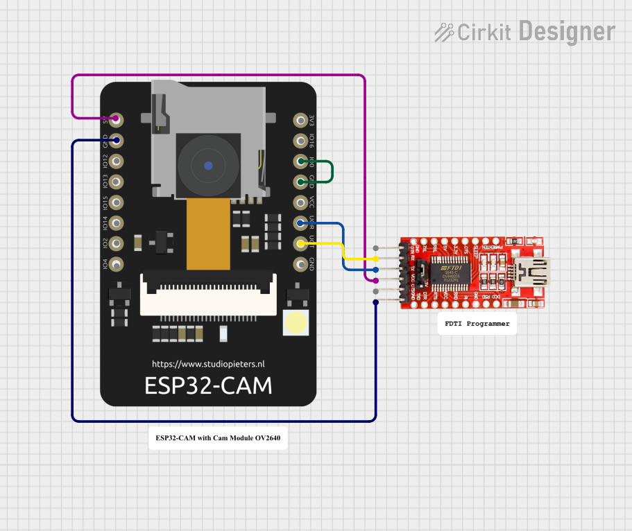
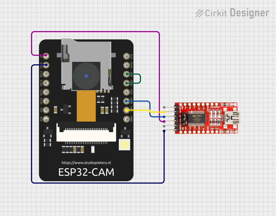
- Programming Mode: To upload code, connect GPIO0 to GND and reset the board. This puts the ESP32-CAM into programming mode.
- Camera Connection: The OV2640 camera module is pre-attached to the ESP32-CAM. Ensure the ribbon cable is securely connected.
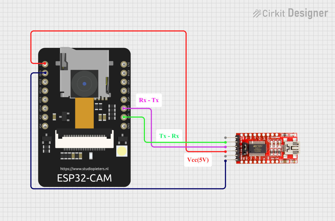
- Serial Communication: Use a USB-to-TTL converter to connect the ESP32-CAM to your computer. Connect TX to RX, RX to TX, and GND to GND.
- Upload Code: Use the Arduino IDE or ESP-IDF to upload your code. Select "AI-Thinker ESP32-CAM" as the board in the Arduino IDE.
Important Considerations
- Heat Management: The ESP32-CAM can get warm during operation. Ensure proper ventilation or use a heatsink if necessary.
- Power Supply: A stable 5V power supply is critical for reliable operation, especially when using Wi-Fi or the camera.
- Antenna: The ESP32-CAM has an onboard PCB antenna. For better range, you can use an external antenna (requires soldering a jumper).
- Boot Mode: Always disconnect GPIO0 from GND after uploading code to run the program.
Example Code for Arduino UNO
Below is an example of how to use the ESP32-CAM to capture an image and serve it over Wi-Fi:
#include <WiFi.h>
#include <esp_camera.h>

// Replace with your Wi-Fi credentials
const char* ssid = "Your_SSID";
const char* password = "Your_PASSWORD";

// Camera configuration
#define PWDN_GPIO_NUM    -1
#define RESET_GPIO_NUM   -1
#define XCLK_GPIO_NUM     0
#define SIOD_GPIO_NUM    26
#define SIOC_GPIO_NUM    27
#define Y9_GPIO_NUM      35
#define Y8_GPIO_NUM      34
#define Y7_GPIO_NUM      39
#define Y6_GPIO_NUM      36
#define Y5_GPIO_NUM      21
#define Y4_GPIO_NUM      19
#define Y3_GPIO_NUM      18
#define Y2_GPIO_NUM       5
#define VSYNC_GPIO_NUM   25
#define HREF_GPIO_NUM    23
#define PCLK_GPIO_NUM    22

void startCameraServer();

void setup() {
  Serial.begin(115200);
  Serial.println();

  // Connect to Wi-Fi
  WiFi.begin(ssid, password);
  while (WiFi.status() != WL_CONNECTED) {
    delay(500);
    Serial.print(".");
  }
  Serial.println("");
  Serial.println("WiFi connected");
  Serial.println("IP address: ");
  Serial.println(WiFi.localIP());

  // Initialize the camera
  camera_config_t config;
  config.ledc_channel = LEDC_CHANNEL_0;
  config.ledc_timer = LEDC_TIMER_0;
  config.pin_d0 = Y2_GPIO_NUM;
  config.pin_d1 = Y3_GPIO_NUM;
  config.pin_d2 = Y4_GPIO_NUM;
  config.pin_d3 = Y5_GPIO_NUM;
  config.pin_d4 = Y6_GPIO_NUM;
  config.pin_d5 = Y7_GPIO_NUM;
  config.pin_d6 = Y8_GPIO_NUM;
  config.pin_d7 = Y9_GPIO_NUM;
  config.pin_xclk = XCLK_GPIO_NUM;
  config.pin_pclk = PCLK_GPIO_NUM;
  config.pin_vsync = VSYNC_GPIO_NUM;
  config.pin_href = HREF_GPIO_NUM;
  config.pin_sscb_sda = SIOD_GPIO_NUM;
  config.pin_sscb_scl = SIOC_GPIO_NUM;
  config.pin_pwdn = PWDN_GPIO_NUM;
  config.pin_reset = RESET_GPIO_NUM;
  config.xclk_freq_hz = 20000000;
  config.pixel_format = PIXFORMAT_JPEG;

  if (!esp_camera_init(&config)) {
    Serial.println("Camera init failed");
    return;
  }

  // Start the camera server
  startCameraServer();
}

void loop() {
  delay(10000); // Keep the server running
}
Troubleshooting and FAQs
Common Issues
Camera Initialization Failed:
- Ensure the ribbon cable is securely connected to the ESP32-CAM.
- Verify that the camera module is not damaged.
- Check the power supply for stability.
Wi-Fi Connection Issues:
- Double-check the SSID and password in your code.
- Ensure the ESP32-CAM is within range of the Wi-Fi router.
Code Upload Fails:
- Confirm that GPIO0 is connected to GND during programming.
- Use a reliable USB-to-TTL converter and ensure proper connections.
Overheating:
- Provide adequate ventilation or use a heatsink to dissipate heat.
Tips for Troubleshooting
- Use the Serial Monitor to debug issues and check for error messages.
- Test the ESP32-CAM with a simple example sketch to verify basic functionality.
- If the board is unresponsive, try resetting it by pressing the reset button.
By following this documentation, you can effectively use the ESP32-CAM in your projects and troubleshoot common issues.