How to Use ICSP PINS: Examples, Pinouts, and Specs
Introduction
ICSP (In-Circuit Serial Programming) pins are an integral feature of microcontrollers, including those from Arduino. These pins provide a means to program the microcontroller after it has been placed in a circuit, allowing for firmware updates, bootloader installations, and direct communication with the microcontroller using an external programmer or another Arduino board.
Explore Projects Built with ICSP PINS

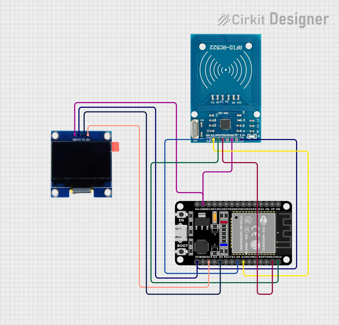

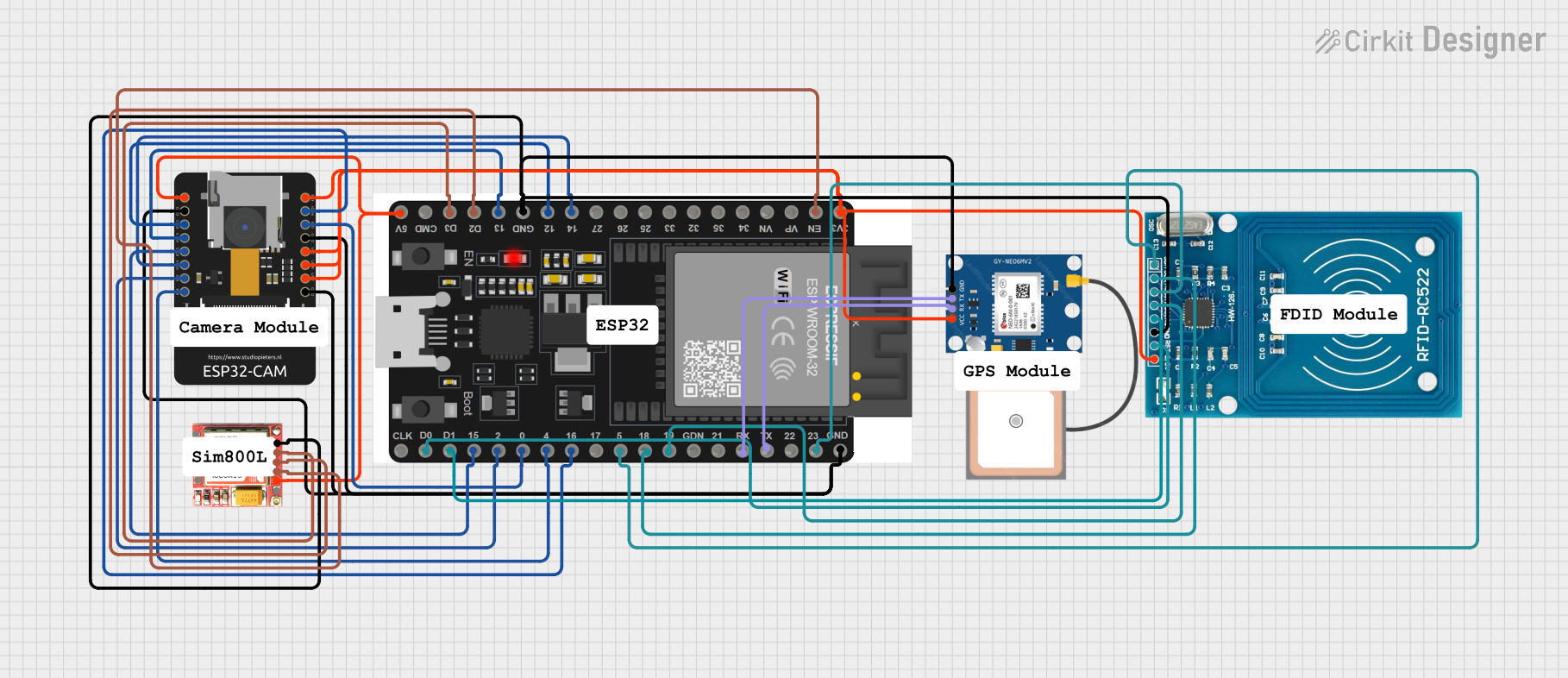
Explore Projects Built with ICSP PINS
Common Applications and Use Cases
- Flashing firmware onto a microcontroller.
- Updating the bootloader on Arduino boards.
- Direct communication for debugging purposes.
- Cloning the firmware from one microcontroller to another.
Technical Specifications
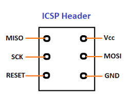
ICSP pins typically consist of a 6-pin interface that includes power, ground, reset, and data transfer lines. Below is a table outlining the pin configuration and descriptions for a standard Arduino ICSP header.
| Pin Number | Name | Description |
|---|---|---|
| 1 | MISO | Master In Slave Out - Used for data transfer from the microcontroller to the external programmer. |
| 2 | VCC | Positive supply voltage - Powers the microcontroller during programming. |
| 3 | SCK | Serial Clock - Provides the clock signal for synchronous data transfer. |
| 4 | MOSI | Master Out Slave In - Used for data transfer to the microcontroller from the external programmer. |
| 5 | RESET | Resets the microcontroller to initiate the programming mode. |
| 6 | GND | Ground - Common reference for the power supply. |
Usage Instructions
How to Use ICSP Pins in a Circuit
Connecting the Programmer:
- Connect the ICSP pins of the Arduino to the corresponding pins of the external programmer or another Arduino configured as an ISP (In-System Programmer).
- Ensure that the pin 1 indicator (often a small dot or notch) on the Arduino aligns with pin 1 on the programmer.
Power Supply:
- Provide power to the VCC and GND pins if the external programmer does not supply power. Be cautious not to exceed the voltage rating of the microcontroller.
Programming:
- Use the appropriate software (e.g., Arduino IDE) to select the correct board and port.
- Choose the correct programmer from the Tools menu.
- Initiate the upload or burn bootloader process as required.
Important Considerations and Best Practices
- Always verify connections before powering up to prevent damage to the microcontroller or programmer.
- Ensure that the microcontroller is not powered from another source during programming to avoid voltage conflicts.
- Use a capacitor between RESET and GND if using another Arduino as an ISP to prevent it from resetting during programming.
Troubleshooting and FAQs
Common Issues
- Programmer Not Recognized: Ensure that all connections are secure and the programmer is correctly selected in the software.
- Error Uploading to Board: Check for correct driver installation and that the correct board and port are selected.
- Power Issues: Verify that the VCC pin is supplied with the correct voltage and that there is a common ground between the programmer and the microcontroller.
Solutions and Tips for Troubleshooting
- Double-check wiring, especially the orientation of the ICSP header.
- Use a multimeter to verify that there is continuity between the ICSP pins and the corresponding pins on the programmer.
- If using another Arduino as an ISP, ensure that the ISP sketch is uploaded and functioning correctly.
FAQs
Q: Can I use the ICSP pins for purposes other than programming? A: Yes, the ICSP pins can also be used for serial communication with other devices.
Q: Do I need to remove the microcontroller from the circuit to program it using ICSP? A: No, one of the main advantages of ICSP is the ability to program the microcontroller while it's still in the circuit.
Q: Is it possible to damage the microcontroller using ICSP? A: If not handled properly, such as by reversing the power supply or exceeding voltage ratings, it is possible to damage the microcontroller.
Example Code for Arduino UNO
Below is an example of how to use another Arduino UNO as an ISP to program a target Arduino UNO using ICSP pins. This code is to be uploaded to the programmer Arduino UNO.
#include <SPI.h>
#include <ArduinoISP.h>

void setup() {
  // Start the serial communication with the computer
  Serial.begin(19200);
  // Ensure that the built-in LED is set as an output
  pinMode(LED_BUILTIN, OUTPUT);
  // Initialize the ArduinoISP
  ArduinoISP.begin();
}

void loop() {
  // Run the Arduino ISP loop function
  ArduinoISP.loop();
}
Remember to connect the ICSP headers of both Arduinos correctly, aligning pin 1 on the programmer to pin 1 on the target, and select "Arduino as ISP" in the Arduino IDE's "Programmer" menu before burning the bootloader or uploading a sketch to the target Arduino.