How to Use StepDownLM2596: Examples, Pinouts, and Specs
Introduction
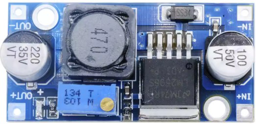
The LM2596 is a step-down (buck) voltage regulator designed to efficiently convert a higher input voltage to a lower output voltage. It is widely used in power supply applications due to its high efficiency and ability to handle up to 3A of output current. The LM2596 is available in both fixed output voltage options (e.g., 3.3V, 5V, 12V) and adjustable versions, making it versatile for a variety of electronic projects.
Explore Projects Built with StepDownLM2596


Explore Projects Built with StepDownLM2596
Common Applications and Use Cases
- Power supply circuits for microcontrollers, sensors, and modules
- Battery-powered devices requiring regulated voltage
- DC-DC converters in automotive and industrial systems
- LED drivers and portable electronics
- Voltage regulation in DIY electronics projects
Technical Specifications
The LM2596 is a robust and efficient voltage regulator with the following key specifications:
| Parameter | Value |
|---|---|
| Input Voltage Range | 4.5V to 40V |
| Output Voltage Range | 1.23V to 37V (adjustable version) |
| Output Current | Up to 3A |
| Efficiency | Up to 92% |
| Switching Frequency | 150 kHz |
| Output Voltage Tolerance | ±4% |
| Operating Temperature | -40°C to +125°C |
| Package Type | TO-220, TO-263 |
Pin Configuration and Descriptions
The LM2596 typically comes in a 5-pin package. Below is the pin configuration:
| Pin Number | Pin Name | Description |
|---|---|---|
| 1 | VIN | Input voltage (4.5V to 40V) |
| 2 | Output | Regulated output voltage |
| 3 | Ground (GND) | Ground connection |
| 4 | Feedback | Feedback pin for adjustable output voltage |
| 5 | ON/OFF | Enable/disable pin (optional, not always used) |
Usage Instructions
How to Use the LM2596 in a Circuit
- Input Voltage: Connect the input voltage (VIN) to the LM2596. Ensure the input voltage is within the range of 4.5V to 40V.
- Output Voltage: For fixed versions, the output voltage is pre-set (e.g., 5V). For adjustable versions, connect a resistor divider to the Feedback pin to set the desired output voltage.
- Capacitors: Place input and output capacitors close to the regulator to ensure stability and reduce noise. Typical values are:
- Input capacitor: 100 µF electrolytic
- Output capacitor: 220 µF electrolytic
- Inductor: Use an appropriate inductor value (e.g., 33 µH) based on the desired output voltage and current.
- Enable Pin: If the ON/OFF pin is used, connect it to a logic signal or leave it floating for continuous operation.
Important Considerations and Best Practices
- Heat Dissipation: The LM2596 can generate heat under high current loads. Use a heatsink or ensure proper ventilation to prevent overheating.
- Input Voltage Margin: Ensure the input voltage is at least 3V higher than the desired output voltage for proper regulation.
- PCB Layout: Minimize the trace length between the input/output capacitors and the regulator to reduce noise and improve stability.
- Load Current: Do not exceed the maximum output current of 3A to avoid damage to the regulator.
Example: Using LM2596 with Arduino UNO
The LM2596 can be used to power an Arduino UNO by stepping down a higher voltage (e.g., 12V) to 5V. Below is an example circuit and Arduino code to demonstrate its use.
Circuit Setup
- Connect a 12V DC power source to the VIN pin of the LM2596.
- Set the output voltage to 5V using the adjustable version of the LM2596.
- Connect the output of the LM2596 to the 5V pin of the Arduino UNO.
- Ensure proper grounding between the LM2596 and the Arduino UNO.
Arduino Code Example
// Example code to blink an LED using Arduino UNO powered by LM2596
// Ensure the LM2596 output is set to 5V before connecting to the Arduino

const int ledPin = 13; // Pin connected to the onboard LED

void setup() {
  pinMode(ledPin, OUTPUT); // Set the LED pin as an output
}

void loop() {
  digitalWrite(ledPin, HIGH); // Turn the LED on
  delay(1000);                // Wait for 1 second
  digitalWrite(ledPin, LOW);  // Turn the LED off
  delay(1000);                // Wait for 1 second
}
Troubleshooting and FAQs
Common Issues and Solutions
Output Voltage Not Stable
- Ensure the input voltage is at least 3V higher than the desired output voltage.
- Check the input and output capacitors for proper values and placement.
Regulator Overheating
- Verify that the load current does not exceed 3A.
- Use a heatsink or improve ventilation around the regulator.
No Output Voltage
- Check all connections, especially the input voltage and ground.
- Ensure the ON/OFF pin is not pulled low (if used).
High Noise or Ripple
- Use low-ESR capacitors for input and output filtering.
- Ensure proper PCB layout with short and wide traces for power connections.
FAQs
Q: Can the LM2596 be used with a battery as the input source?
A: Yes, the LM2596 can be used with batteries as long as the input voltage is within the 4.5V to 40V range.
Q: How do I adjust the output voltage on the adjustable version?
A: Use a resistor divider network connected to the Feedback pin. Refer to the datasheet for the formula to calculate the resistor values.
Q: Is the LM2596 suitable for powering sensitive devices?
A: Yes, but ensure proper filtering with capacitors to minimize noise and ripple.
Q: Can I use the LM2596 for AC to DC conversion?
A: No, the LM2596 is a DC-DC converter and requires a DC input. Use a rectifier and filter circuit to convert AC to DC before using the LM2596.