Cirkit Designer Logo
Cirkit Designer
Your all-in-one circuit design IDE
Home / 
Component Documentation

How to Use ESP32 DevKitC V4: Examples, Pinouts, and Specs

Image of ESP32 DevKitC V4
Cirkit Designer LogoDesign with ESP32 DevKitC V4 in Cirkit Designer

Introduction

The ESP32 DevKitC V4 is a compact and versatile development board designed by Espressif. It features the ESP32-WROOM-32U module, which integrates a powerful dual-core processor, Wi-Fi, and Bluetooth capabilities. This board is ideal for Internet of Things (IoT) applications, smart devices, and rapid prototyping. Its small form factor and rich set of GPIO pins make it suitable for a wide range of projects, from home automation to industrial control systems.

Explore Projects Built with ESP32 DevKitC V4

Use Cirkit Designer to design, explore, and prototype these projects online. Some projects support real-time simulation. Click "Open Project" to start designing instantly!
ESP32 Devkit V1 and OLED Display Bitmap Viewer
Image of Esp32_monochromeimage: A project utilizing ESP32 DevKitC V4 in a practical application
This circuit consists of an ESP32 Devkit V1 microcontroller connected to a 1.3" OLED display via I2C communication. The ESP32 initializes the OLED display and renders a predefined bitmap image on it.
Cirkit Designer LogoOpen Project in Cirkit Designer
ESP32-Based Smart Agriculture System with LoRa Communication
Image of Soil Monitoring Device: A project utilizing ESP32 DevKitC V4 in a practical application
This circuit features an ESP32 Devkit V1 microcontroller as the central processing unit, interfacing with various sensors including a PH Meter, an NPK Soil Sensor, and a Soil Moisture Sensor for environmental data collection. It also includes an EBYTE LoRa E220 module for wireless communication. Power management is handled by a Step Up Boost Power Converter, which is connected to a 12V Battery, stepping up the voltage to power the ESP32 and sensors, with common ground connections throughout the circuit.
Cirkit Designer LogoOpen Project in Cirkit Designer
ESP32 and Logic Level Converter-Based Wi-Fi Controlled Interface
Image of Toshiba AC ESP32 devkit v1: A project utilizing ESP32 DevKitC V4 in a practical application
This circuit features an ESP32 Devkit V1 microcontroller connected to a Bi-Directional Logic Level Converter, which facilitates voltage level shifting between the ESP32 and external components. The ESP32 is powered through its VIN pin via an alligator clip cable, and the logic level converter is connected to various pins on the ESP32 to manage different voltage levels for communication.
Cirkit Designer LogoOpen Project in Cirkit Designer
ESP32-Based Environmental Monitoring and Alert System with Solar Charging
Image of mark: A project utilizing ESP32 DevKitC V4 in a practical application
This circuit features an ESP32 Devkit V1 microcontroller connected to various sensors and modules for monitoring and communication purposes. It includes an MQ-2 gas sensor and a DHT11 temperature and humidity sensor, both interfaced with the ESP32 for environmental data collection. The circuit is powered by a 12V battery, regulated to 5V by step-down converters, and includes a solar charge controller connected to a solar panel for battery charging, a UPS module for power management, and a SIM900A module for GSM communication. Additionally, there is a WS2812 RGB LED strip for visual feedback and a piezo buzzer for audio alerts, both controlled by the ESP32.
Cirkit Designer LogoOpen Project in Cirkit Designer

Explore Projects Built with ESP32 DevKitC V4

Use Cirkit Designer to design, explore, and prototype these projects online. Some projects support real-time simulation. Click "Open Project" to start designing instantly!
Image of Esp32_monochromeimage: A project utilizing ESP32 DevKitC V4 in a practical application
ESP32 Devkit V1 and OLED Display Bitmap Viewer
This circuit consists of an ESP32 Devkit V1 microcontroller connected to a 1.3" OLED display via I2C communication. The ESP32 initializes the OLED display and renders a predefined bitmap image on it.
Cirkit Designer LogoOpen Project in Cirkit Designer
Image of Soil Monitoring Device: A project utilizing ESP32 DevKitC V4 in a practical application
ESP32-Based Smart Agriculture System with LoRa Communication
This circuit features an ESP32 Devkit V1 microcontroller as the central processing unit, interfacing with various sensors including a PH Meter, an NPK Soil Sensor, and a Soil Moisture Sensor for environmental data collection. It also includes an EBYTE LoRa E220 module for wireless communication. Power management is handled by a Step Up Boost Power Converter, which is connected to a 12V Battery, stepping up the voltage to power the ESP32 and sensors, with common ground connections throughout the circuit.
Cirkit Designer LogoOpen Project in Cirkit Designer
Image of Toshiba AC ESP32 devkit v1: A project utilizing ESP32 DevKitC V4 in a practical application
ESP32 and Logic Level Converter-Based Wi-Fi Controlled Interface
This circuit features an ESP32 Devkit V1 microcontroller connected to a Bi-Directional Logic Level Converter, which facilitates voltage level shifting between the ESP32 and external components. The ESP32 is powered through its VIN pin via an alligator clip cable, and the logic level converter is connected to various pins on the ESP32 to manage different voltage levels for communication.
Cirkit Designer LogoOpen Project in Cirkit Designer
Image of mark: A project utilizing ESP32 DevKitC V4 in a practical application
ESP32-Based Environmental Monitoring and Alert System with Solar Charging
This circuit features an ESP32 Devkit V1 microcontroller connected to various sensors and modules for monitoring and communication purposes. It includes an MQ-2 gas sensor and a DHT11 temperature and humidity sensor, both interfaced with the ESP32 for environmental data collection. The circuit is powered by a 12V battery, regulated to 5V by step-down converters, and includes a solar charge controller connected to a solar panel for battery charging, a UPS module for power management, and a SIM900A module for GSM communication. Additionally, there is a WS2812 RGB LED strip for visual feedback and a piezo buzzer for audio alerts, both controlled by the ESP32.
Cirkit Designer LogoOpen Project in Cirkit Designer

Common Applications and Use Cases

  • IoT devices and smart home systems
  • Wireless sensor networks
  • Bluetooth-enabled applications
  • Prototyping and development of embedded systems
  • Robotics and automation projects
  • Data logging and remote monitoring

Technical Specifications

Key Technical Details

Parameter Value
Microcontroller ESP32 (dual-core Xtensa LX6 processor)
Clock Speed Up to 240 MHz
Flash Memory 4 MB (integrated in ESP32-WROOM-32U)
RAM 520 KB SRAM
Wireless Connectivity Wi-Fi 802.11 b/g/n, Bluetooth v4.2 BR/EDR
Operating Voltage 3.3V
Input Voltage (via USB) 5V
GPIO Pins 30 (multipurpose, including ADC, PWM, etc.)
Communication Interfaces UART, SPI, I2C, I2S, CAN, PWM
Dimensions 54 mm x 27 mm

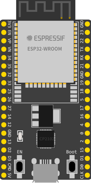
Pin Configuration and Descriptions

The ESP32 DevKitC V4 has a total of 30 GPIO pins, which are multiplexed for various functions. Below is the pinout description:

Pin Number Pin Name Functionality
1 EN Reset the chip (active high)
2 IO0 GPIO0, used for boot mode selection
3 IO1 GPIO1, UART TXD0
4 IO2 GPIO2, ADC, PWM, Touch Sensor
5 IO3 GPIO3, UART RXD0
6 IO4 GPIO4, ADC, PWM, Touch Sensor
7 IO5 GPIO5, ADC, PWM, Touch Sensor
8 IO12 GPIO12, ADC, PWM, Touch Sensor
9 IO13 GPIO13, ADC, PWM, Touch Sensor
10 IO14 GPIO14, ADC, PWM, Touch Sensor
11 IO15 GPIO15, ADC, PWM, Touch Sensor
12 IO16 GPIO16, UART RXD2
13 IO17 GPIO17, UART TXD2
14 IO18 GPIO18, SPI CLK
15 IO19 GPIO19, SPI MISO
16 IO21 GPIO21, I2C SDA
17 IO22 GPIO22, I2C SCL
18 IO23 GPIO23, SPI MOSI
19 IO25 GPIO25, ADC, DAC
20 IO26 GPIO26, ADC, DAC
21 IO27 GPIO27, ADC, PWM
22 IO32 GPIO32, ADC, Touch Sensor
23 IO33 GPIO33, ADC, Touch Sensor
24 IO34 GPIO34, ADC (input only)
25 IO35 GPIO35, ADC (input only)
26 IO36 GPIO36, ADC (input only)
27 IO39 GPIO39, ADC (input only)

Usage Instructions

How to Use the ESP32 DevKitC V4 in a Circuit

  1. Powering the Board:

    • The board can be powered via the micro-USB port (5V input).
    • Alternatively, you can supply 3.3V directly to the 3V3 pin.
  2. Programming the Board:

    • The ESP32 DevKitC V4 can be programmed using the Arduino IDE, Espressif's ESP-IDF, or other compatible environments.
    • Install the necessary drivers and libraries for the ESP32 in your development environment.
  3. Connecting Peripherals:

    • Use the GPIO pins to connect sensors, actuators, or other peripherals.
    • Ensure that the voltage levels of connected devices are compatible with the 3.3V logic of the ESP32.
  4. Uploading Code:

    • Connect the board to your computer via USB.
    • Select the appropriate board and port in your IDE.
    • Write or load your code and upload it to the ESP32.

Important Considerations and Best Practices

  • Voltage Levels: The GPIO pins operate at 3.3V. Avoid applying 5V directly to the pins to prevent damage.
  • Boot Mode: To enter bootloader mode, hold the BOOT button while pressing the EN (reset) button.
  • Power Supply: Ensure a stable power supply to avoid unexpected resets or malfunctions.
  • Wi-Fi and Bluetooth: Avoid placing the board in metal enclosures, as this can interfere with wireless communication.

Example Code for Arduino IDE

Below is an example of how to blink an LED connected to GPIO2:

// Define the GPIO pin for the LED
const int ledPin = 2;

void setup() {
  // Set the LED pin as an output
  pinMode(ledPin, OUTPUT);
}

void loop() {
  // Turn the LED on
  digitalWrite(ledPin, HIGH);
  delay(1000); // Wait for 1 second

  // Turn the LED off
  digitalWrite(ledPin, LOW);
  delay(1000); // Wait for 1 second
}

Troubleshooting and FAQs

Common Issues and Solutions

  1. The board is not detected by the computer:

    • Ensure the USB cable is functional and supports data transfer.
    • Install the correct USB-to-serial driver for the ESP32.
  2. Code upload fails:

    • Check that the correct board and port are selected in the IDE.
    • Hold the BOOT button while uploading the code to enter bootloader mode.
  3. Wi-Fi connection issues:

    • Verify the SSID and password in your code.
    • Ensure the router is within range and supports 2.4 GHz Wi-Fi.
  4. GPIO pin not working as expected:

    • Check if the pin is being used for another function (e.g., ADC, PWM).
    • Avoid using pins reserved for internal functions (e.g., GPIO6-GPIO11 for flash memory).

FAQs

  • Q: Can I power the ESP32 DevKitC V4 with a battery?
    A: Yes, you can use a 3.7V LiPo battery with a voltage regulator to supply 3.3V to the 3V3 pin.

  • Q: What is the maximum current output of the GPIO pins?
    A: Each GPIO pin can source or sink up to 12 mA safely.

  • Q: Can I use the ESP32 DevKitC V4 with MicroPython?
    A: Yes, the ESP32 supports MicroPython. You can flash the MicroPython firmware to the board and use it for development.

  • Q: How do I reset the board?
    A: Press the EN button to reset the board.