Cirkit Designer Logo
Cirkit Designer
Your all-in-one circuit design IDE
Home / 
Component Documentation

How to Use 28BYJ-48 Stepper Motor: Examples, Pinouts, and Specs

Image of 28BYJ-48 Stepper Motor
Cirkit Designer LogoDesign with 28BYJ-48 Stepper Motor in Cirkit Designer

Introduction

The 28BYJ-48 stepper motor is a small, lightweight, and cost-effective unipolar stepper motor commonly used in DIY projects, robotics, and automation systems. It is designed for applications requiring precise rotational movement and control. With its 4-phase coil arrangement and 5-wire connection, it offers a high degree of control and is suitable for a wide range of applications.

Explore Projects Built with 28BYJ-48 Stepper Motor

Use Cirkit Designer to design, explore, and prototype these projects online. Some projects support real-time simulation. Click "Open Project" to start designing instantly!
Arduino Mega 2560-Controlled Stepper Motors with RFID Access and Traffic Light Indication
Image of Copy of test: A project utilizing 28BYJ-48 Stepper Motor in a practical application
This circuit controls two 28BYJ-48 stepper motors using A4988 stepper motor driver carriers, interfaced with an Arduino Mega 2560 microcontroller. It features an RFID-RC522 module for RFID reading, a 16x4 LCD display with I2C interface for user interaction, and a piezo speaker for audio feedback. Additionally, there is a traffic light module controlled by the Arduino, and a 48V to 5V converter to step down voltage for the logic levels. The power supply provides 12V to the motor drivers and is connected to a standard power outlet.
Cirkit Designer LogoOpen Project in Cirkit Designer
RFID-Activated Traffic Light Controller with Auditory Feedback Using Arduino Mega
Image of test: A project utilizing 28BYJ-48 Stepper Motor in a practical application
This circuit is designed to control two 28BYJ-48 stepper motors using A4988 stepper motor driver carriers, with an Arduino Mega 2560 as the central microcontroller. It includes an RFID-RC522 module for RFID reading, an LCD display for user interface, and a traffic light and piezo speaker for visual and audio signaling. The circuit is powered by a 12V 5A power supply, which is stepped down to 5V for logic level components, and it interfaces with a power outlet for AC to DC conversion.
Cirkit Designer LogoOpen Project in Cirkit Designer
Arduino-Controlled 28BYJ-48 Stepper Motor with ULN2003 Driver
Image of Act: A project utilizing 28BYJ-48 Stepper Motor in a practical application
This circuit controls a 28BYJ-48 stepper motor using an Arduino UNO and a ULN2003A breakout board. The Arduino is programmed to drive the stepper motor with a specific number of steps received via its serial interface, allowing for precise rotational movement control. The ULN2003A interfaces between the low-current Arduino output pins and the higher-current requirements of the stepper motor coils.
Cirkit Designer LogoOpen Project in Cirkit Designer
Arduino UNO Controlled Stepper Motor with ULN2003A Driver
Image of Arduino-Controlled 28BYJ-48 Stepper Motor with ULN2003 Driver: A project utilizing 28BYJ-48 Stepper Motor in a practical application
This circuit controls a 28BYJ-48 stepper motor using an Arduino UNO and a ULN2003A driver board. The Arduino sends control signals to the ULN2003A, which then drives the stepper motor based on commands received via the serial interface.
Cirkit Designer LogoOpen Project in Cirkit Designer

Explore Projects Built with 28BYJ-48 Stepper Motor

Use Cirkit Designer to design, explore, and prototype these projects online. Some projects support real-time simulation. Click "Open Project" to start designing instantly!
Image of Copy of test: A project utilizing 28BYJ-48 Stepper Motor in a practical application
Arduino Mega 2560-Controlled Stepper Motors with RFID Access and Traffic Light Indication
This circuit controls two 28BYJ-48 stepper motors using A4988 stepper motor driver carriers, interfaced with an Arduino Mega 2560 microcontroller. It features an RFID-RC522 module for RFID reading, a 16x4 LCD display with I2C interface for user interaction, and a piezo speaker for audio feedback. Additionally, there is a traffic light module controlled by the Arduino, and a 48V to 5V converter to step down voltage for the logic levels. The power supply provides 12V to the motor drivers and is connected to a standard power outlet.
Cirkit Designer LogoOpen Project in Cirkit Designer
Image of test: A project utilizing 28BYJ-48 Stepper Motor in a practical application
RFID-Activated Traffic Light Controller with Auditory Feedback Using Arduino Mega
This circuit is designed to control two 28BYJ-48 stepper motors using A4988 stepper motor driver carriers, with an Arduino Mega 2560 as the central microcontroller. It includes an RFID-RC522 module for RFID reading, an LCD display for user interface, and a traffic light and piezo speaker for visual and audio signaling. The circuit is powered by a 12V 5A power supply, which is stepped down to 5V for logic level components, and it interfaces with a power outlet for AC to DC conversion.
Cirkit Designer LogoOpen Project in Cirkit Designer
Image of Act: A project utilizing 28BYJ-48 Stepper Motor in a practical application
Arduino-Controlled 28BYJ-48 Stepper Motor with ULN2003 Driver
This circuit controls a 28BYJ-48 stepper motor using an Arduino UNO and a ULN2003A breakout board. The Arduino is programmed to drive the stepper motor with a specific number of steps received via its serial interface, allowing for precise rotational movement control. The ULN2003A interfaces between the low-current Arduino output pins and the higher-current requirements of the stepper motor coils.
Cirkit Designer LogoOpen Project in Cirkit Designer
Image of Arduino-Controlled 28BYJ-48 Stepper Motor with ULN2003 Driver: A project utilizing 28BYJ-48 Stepper Motor in a practical application
Arduino UNO Controlled Stepper Motor with ULN2003A Driver
This circuit controls a 28BYJ-48 stepper motor using an Arduino UNO and a ULN2003A driver board. The Arduino sends control signals to the ULN2003A, which then drives the stepper motor based on commands received via the serial interface.
Cirkit Designer LogoOpen Project in Cirkit Designer

Common Applications and Use Cases

  • Precision movement control in robotics
  • Automated equipment such as 3D printers and CNC machines
  • Camera pan and tilt mechanisms
  • Time-lapse photography rigs
  • Small positioning devices

Technical Specifications

Key Technical Details

  • Voltage: 5V DC
  • Current: 92 mA (no-load)
  • Step Angle: 5.625°/64 (0.0879° per step)
  • Resistance: 50 ohms per phase
  • Insulation Resistance: >10M ohms at 500V DC
  • Dielectric Strength: 600V AC for 1 sec
  • Pull-in Torque: 300 gf-cm

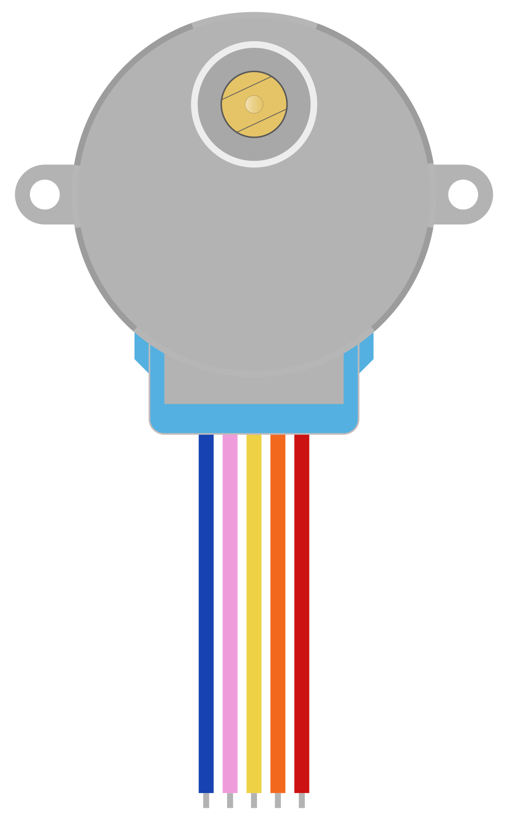
Pin Configuration and Descriptions

Pin Number Wire Color Description
1 Red Common VCC (5V)
2 Blue Coil 1
3 Pink Coil 2
4 Yellow Coil 3
5 Orange Coil 4

Usage Instructions

How to Use the Component in a Circuit

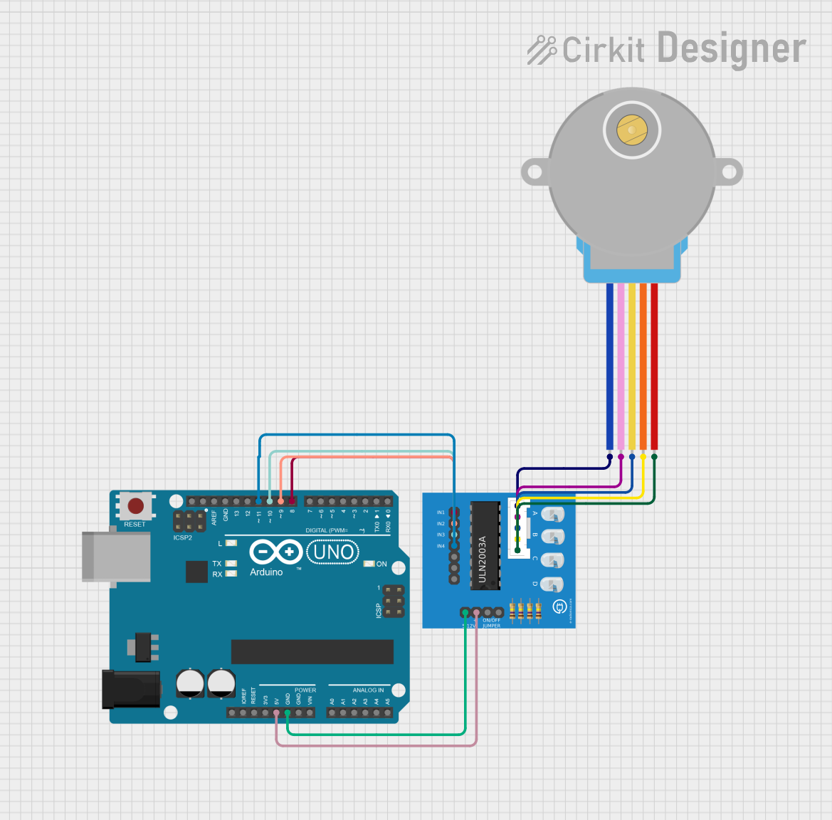
  1. Power Supply: Connect the red wire to a 5V power supply.
  2. Control Wires: Connect the blue, pink, yellow, and orange wires to the control pins of a stepper motor driver or directly to a microcontroller if you are using one that can handle the required current.
  3. Microcontroller Connection: If using an Arduino UNO, you can connect the control wires to digital pins 8 through 11, for example.

Important Considerations and Best Practices

  • Always use a suitable driver circuit or a microcontroller with enough current capacity to drive the motor.
  • Avoid stalling or overloading the motor as it may lead to overheating and damage.
  • Use a decoupling capacitor across the power supply to minimize electrical noise.
  • Start with slow step rates and gradually increase as needed to avoid missing steps.

Example Code for Arduino UNO

#include <Stepper.h>

// Define the number of steps per revolution
const int stepsPerRevolution = 2048;

// Initialize the stepper library on pins 8 through 11
Stepper myStepper(stepsPerRevolution, 8, 10, 9, 11);

void setup() {
  // Set the speed (rpm) of the motor
  myStepper.setSpeed(15);
}

void loop() {
  // Step one revolution in one direction:
  myStepper.step(stepsPerRevolution);
  delay(1000);

  // Step one revolution in the other direction:
  myStepper.step(-stepsPerRevolution);
  delay(1000);
}

Note: The Stepper library is used for controlling the stepper motor with an Arduino. The stepsPerRevolution value is set to 2048, which corresponds to the number of steps the motor needs to make a full revolution.

Troubleshooting and FAQs

Common Issues Users Might Face

  • Motor not rotating: Check the wiring and ensure that the power supply is adequate and correctly connected.
  • Motor skipping steps or stalling: This could be due to running the motor too fast or overloading it. Reduce the speed or the load on the motor.
  • Motor getting hot: Ensure that the current supplied to the motor does not exceed the recommended rating.

Solutions and Tips for Troubleshooting

  • Double-check all connections and wire colors to ensure they match the pin configuration.
  • Start with a low speed to test the motor and gradually increase as needed.
  • If the motor is not functioning correctly, try reducing the load or changing the step sequence.

FAQs

Q: Can I run the 28BYJ-48 motor at a higher voltage? A: Running the motor at a higher voltage than recommended may increase its speed and torque but can also lead to overheating and reduced lifespan. It is best to use the motor within its specified voltage range.

Q: How can I reverse the direction of the motor? A: To reverse the direction, you can reverse the sequence of the control signals or simply call the step() function with a negative number of steps.

Q: What is the maximum speed of the 28BYJ-48 stepper motor? A: The maximum speed depends on the voltage and the load but is typically around 15-20 rotations per minute (rpm) when driven at 5V.

Q: Can I control the 28BYJ-48 stepper motor without a driver? A: While it is possible to control the motor directly from a microcontroller, using a dedicated stepper motor driver is recommended for better performance and to protect the microcontroller from excessive current draw.