How to Use 7-Segment Panel Voltmeter: Examples, Pinouts, and Specs
Introduction
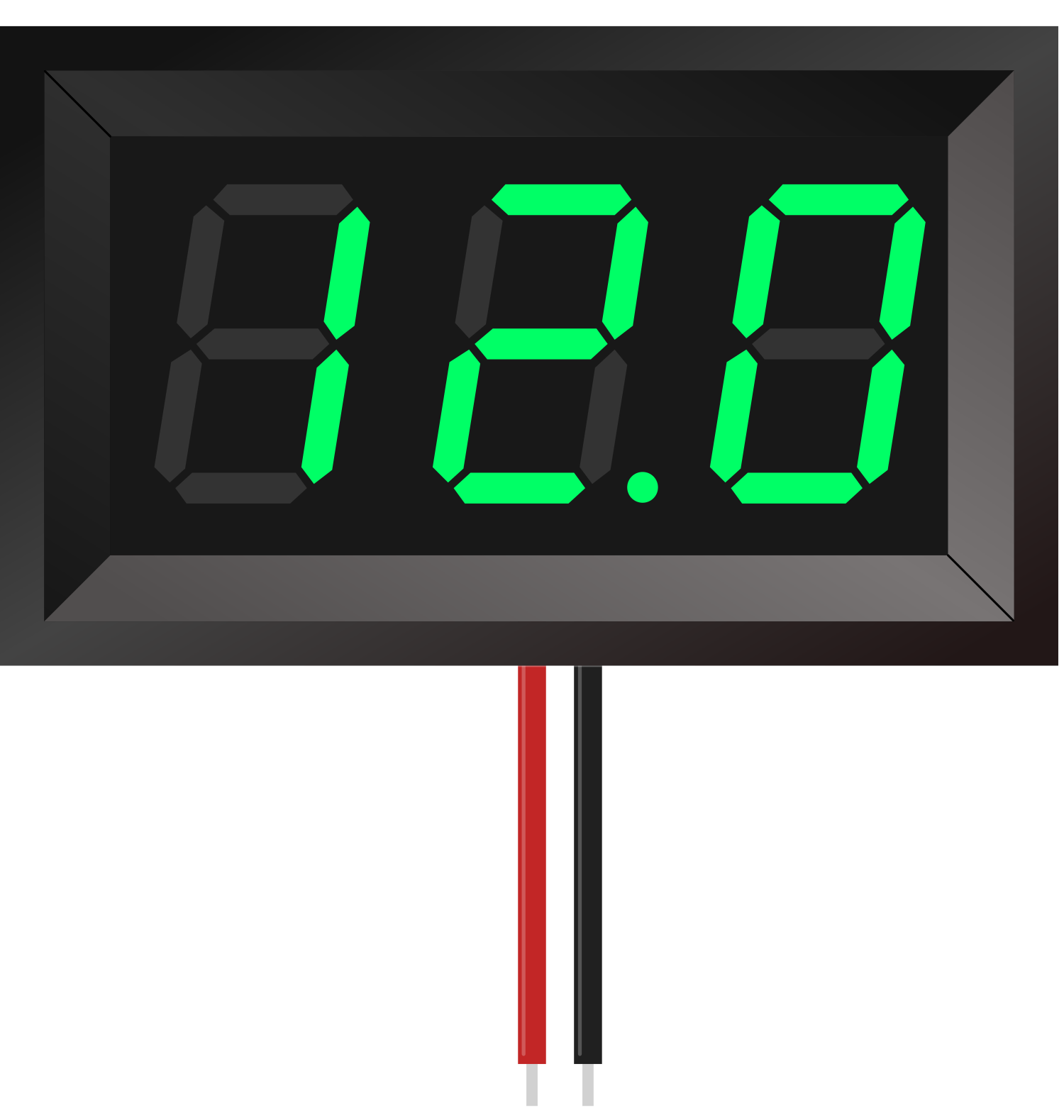
A 7-segment panel voltmeter is an electronic device used to measure and display voltage levels in a circuit. It features a digital display made up of seven segments that illuminate to represent numerical values, providing a clear and easy-to-read output of the measured voltage. These devices are compact, reliable, and widely used in various applications.
Explore Projects Built with 7-Segment Panel Voltmeter

Explore Projects Built with 7-Segment Panel Voltmeter
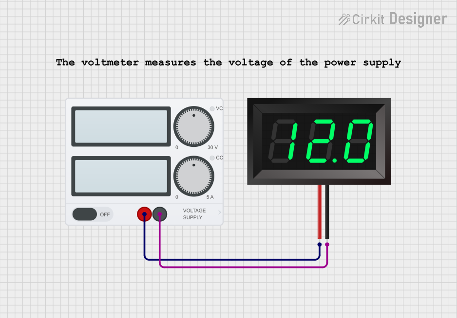
Common Applications and Use Cases
- Monitoring voltage levels in power supplies
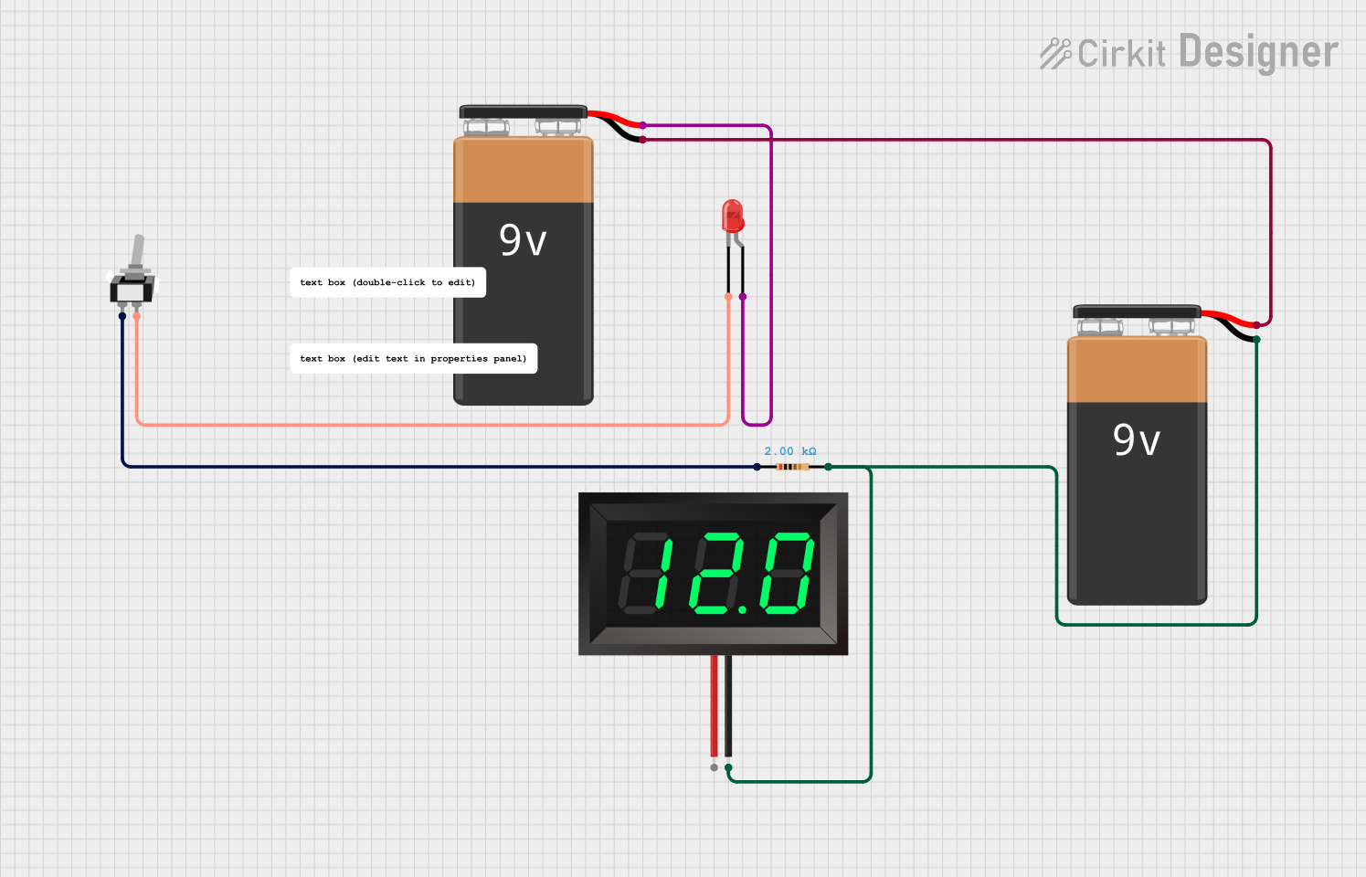
- Battery voltage measurement
- DIY electronics projects
- Industrial equipment and control panels
- Automotive voltage monitoring
Technical Specifications
Below are the key technical details for a typical 7-segment panel voltmeter:
| Parameter | Specification |
|---|---|
| Operating Voltage | 4.5V to 30V DC |
| Measurement Range | 0V to 100V DC (varies by model) |
| Display Type | 7-segment LED |
| Display Color | Red, Green, Blue (varies by model) |
| Accuracy | ±1% (typical) |
| Input Impedance | >100kΩ |
| Refresh Rate | ~200ms |
| Power Consumption | <20mA |
| Dimensions | ~48mm x 29mm x 21mm |
Pin Configuration and Descriptions
The 7-segment panel voltmeter typically has three pins for connection:
| Pin | Name | Description |
|---|---|---|
| 1 | VCC | Positive power supply input (4.5V to 30V DC) |
| 2 | GND | Ground connection |
| 3 | VIN | Voltage input to be measured (0V to 100V DC) |
Note: Some models may have additional pins for features like calibration or external power supply. Always refer to the specific datasheet for your model.
Usage Instructions
How to Use the Component in a Circuit
Power the Voltmeter:
- Connect the
VCCpin to a DC power source (4.5V to 30V). - Connect the
GNDpin to the ground of the power source.
- Connect the
Connect the Voltage to Be Measured:
- Attach the
VINpin to the positive terminal of the voltage source you want to measure. - Ensure the negative terminal of the voltage source is connected to the same ground as the voltmeter.
- Attach the
Observe the Display:
- The measured voltage will be displayed on the 7-segment LED panel in real-time.
Important Considerations and Best Practices
- Voltage Range: Ensure the input voltage to
VINdoes not exceed the specified measurement range of the voltmeter. Exceeding this range may damage the device. - Power Supply: Use a stable DC power supply within the operating voltage range to avoid erratic readings.
- Polarity: Always connect the pins with the correct polarity. Reversing the connections may damage the voltmeter.
- Mounting: Secure the voltmeter in a panel or enclosure to protect it from physical damage and environmental factors.
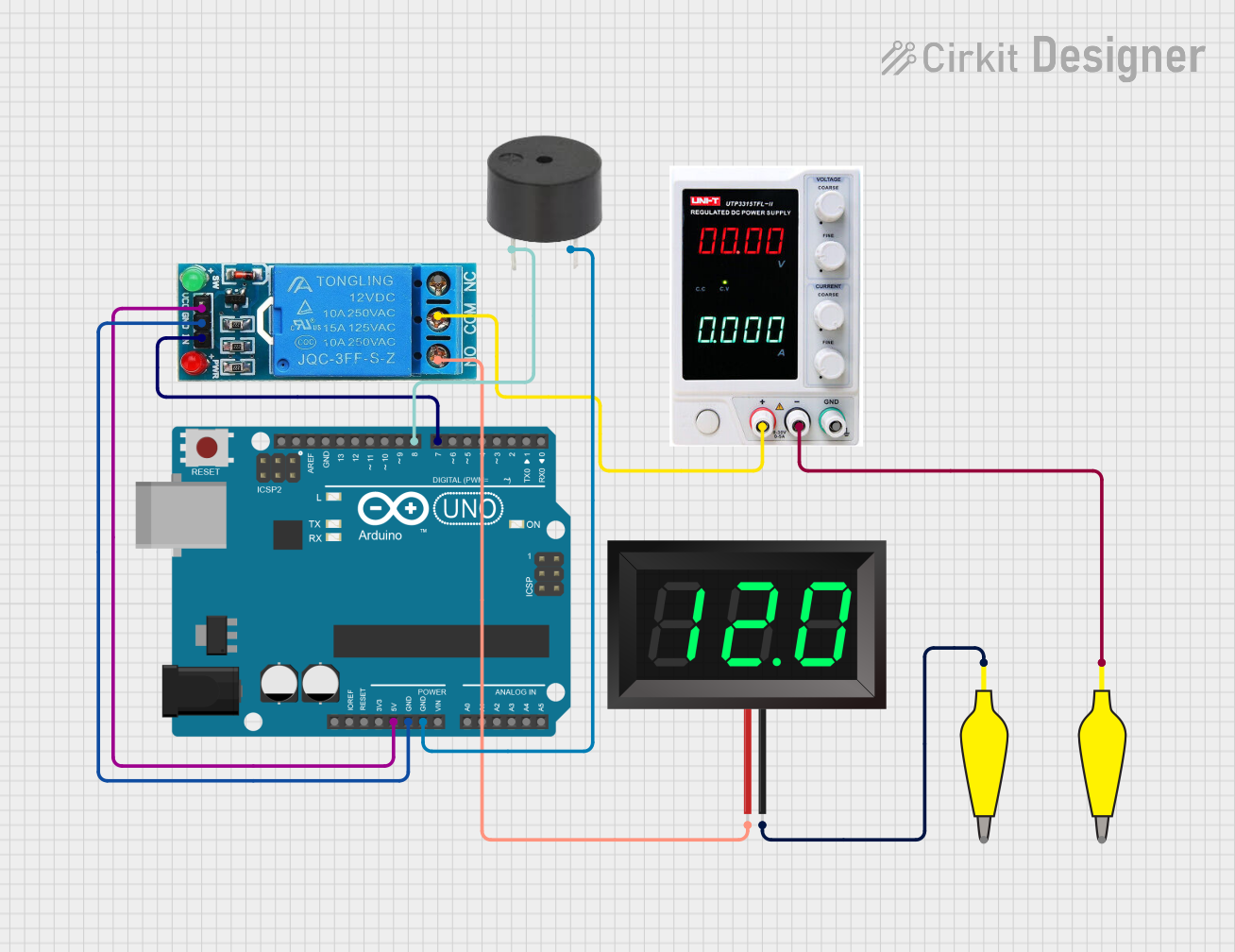
Example: Connecting to an Arduino UNO
The 7-segment panel voltmeter can be used alongside an Arduino UNO to monitor voltage levels in a circuit. Below is an example of how to connect and use the voltmeter:
Circuit Connections
- Connect the
VCCpin of the voltmeter to the 5V pin on the Arduino. - Connect the
GNDpin of the voltmeter to the GND pin on the Arduino. - Connect the
VINpin of the voltmeter to the voltage source you want to measure.
Arduino Code Example
The following code demonstrates how to measure voltage using the Arduino's analog input and display it on the serial monitor. The 7-segment panel voltmeter can be used to cross-check the readings.
// Define the analog pin connected to the voltage divider
const int voltagePin = A0;

// Define the reference voltage of the Arduino (5V for most models)
const float referenceVoltage = 5.0;

// Define the voltage divider ratio (adjust based on your circuit)
const float dividerRatio = 11.0; // Example: 10kΩ and 1kΩ resistors

void setup() {
  Serial.begin(9600); // Initialize serial communication
}

void loop() {
  // Read the analog value from the voltage pin
  int analogValue = analogRead(voltagePin);

  // Convert the analog value to a voltage
  float measuredVoltage = (analogValue / 1023.0) * referenceVoltage * dividerRatio;

  // Print the measured voltage to the serial monitor
  Serial.print("Measured Voltage: ");
  Serial.print(measuredVoltage);
  Serial.println(" V");

  delay(500); // Wait for 500ms before the next reading
}
Note: The Arduino cannot directly measure voltages above 5V. Use a voltage divider to step down the voltage before connecting it to the Arduino's analog pin.
Troubleshooting and FAQs
Common Issues and Solutions
No Display on the Voltmeter:
- Cause: Incorrect power supply or loose connections.
- Solution: Verify that the
VCCandGNDpins are properly connected to a DC power source within the operating voltage range.
Inaccurate Voltage Readings:
- Cause: Input voltage exceeds the measurement range or poor connections.
- Solution: Ensure the input voltage is within the specified range and check all connections for stability.
Flickering Display:
- Cause: Unstable power supply or electrical noise.
- Solution: Use a regulated power supply and add decoupling capacitors if necessary.
Voltmeter Not Responding to Input Voltage:
- Cause: Incorrect polarity or damaged device.
- Solution: Double-check the polarity of the connections. If the issue persists, replace the voltmeter.
FAQs
Q1: Can the voltmeter measure AC voltage?
A1: No, the 7-segment panel voltmeter is designed for DC voltage measurement only. For AC voltage, use an appropriate AC voltmeter.
Q2: Can I use the voltmeter with a 3.3V power supply?
A2: Most models require a minimum of 4.5V for operation. Check the datasheet for your specific model to confirm compatibility.
Q3: How do I calibrate the voltmeter?
A3: Some models include a calibration potentiometer. Refer to the user manual for calibration instructions.
Q4: Can I use the voltmeter to measure the voltage of its own power supply?
A4: Yes, as long as the power supply voltage is within the measurement range of the voltmeter.