How to Use 156:1 Metal Gearmotor 20Dx44L mm 6V CB: Examples, Pinouts, and Specs
Introduction
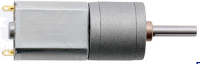
The 156:1 Metal Gearmotor 20Dx44L mm 6V CB (Manufacturer Part ID: 3706) is a compact, high-performance gearmotor designed by Pololu. It features a 20 mm diameter and 44 mm length, making it ideal for applications requiring high torque and low speed. This gearmotor operates at 6V and is well-suited for robotics, automation systems, and other precision motion control projects.
Explore Projects Built with 156:1 Metal Gearmotor 20Dx44L mm 6V CB


Explore Projects Built with 156:1 Metal Gearmotor 20Dx44L mm 6V CB
Common Applications
- Robotics (e.g., driving wheels or actuators)
- Automated systems (e.g., conveyor belts, small lifts)
- Precision motion control in hobbyist and industrial projects
- Educational projects involving motorized mechanisms
Technical Specifications
Below are the key technical details of the 156:1 Metal Gearmotor:
| Parameter | Value |
|---|---|
| Gear Ratio | 156:1 |
| Operating Voltage | 6V |
| No-Load Speed (at 6V) | 100 RPM |
| Stall Torque (at 6V) | 2.5 kg·cm (0.245 N·m) |
| Stall Current (at 6V) | 1.6 A |
| No-Load Current (at 6V) | 0.13 A |
| Shaft Diameter | 4 mm |
| Shaft Length | 18 mm |
| Motor Dimensions | 20 mm (diameter) x 44 mm (length) |
| Weight | 50 g |
Pin Configuration and Descriptions
The motor has two terminals for electrical connections. These terminals are used to control the motor's direction and speed.
| Pin/Terminal | Description |
|---|---|
| Terminal 1 | Motor power input (connect to positive voltage) |
| Terminal 2 | Motor power input (connect to ground or negative voltage) |
Note: Reversing the polarity of the terminals will reverse the motor's rotation direction.
Usage Instructions
How to Use the Component in a Circuit
- Power Supply: Connect the motor to a 6V DC power source. Ensure the power supply can provide sufficient current (at least 1.6 A for stall conditions).
- Motor Driver: Use a motor driver or H-bridge circuit to control the motor's speed and direction. Directly connecting the motor to a microcontroller is not recommended due to high current requirements.
- Polarity Control: To change the motor's rotation direction, reverse the polarity of the voltage applied to the terminals.
- PWM Control: For speed control, use a PWM (Pulse Width Modulation) signal from a motor driver or microcontroller.
Important Considerations and Best Practices
- Current Handling: Ensure your motor driver or power supply can handle the stall current (1.6 A) to avoid damage.
- Heat Dissipation: Prolonged operation at high loads may cause the motor to heat up. Allow for adequate cooling or limit continuous operation under heavy loads.
- Mounting: Secure the motor using the mounting holes provided on the gearbox. Avoid applying excessive force to the shaft.
- Decoupling Capacitors: To reduce electrical noise, consider adding a 0.1 µF ceramic capacitor across the motor terminals.
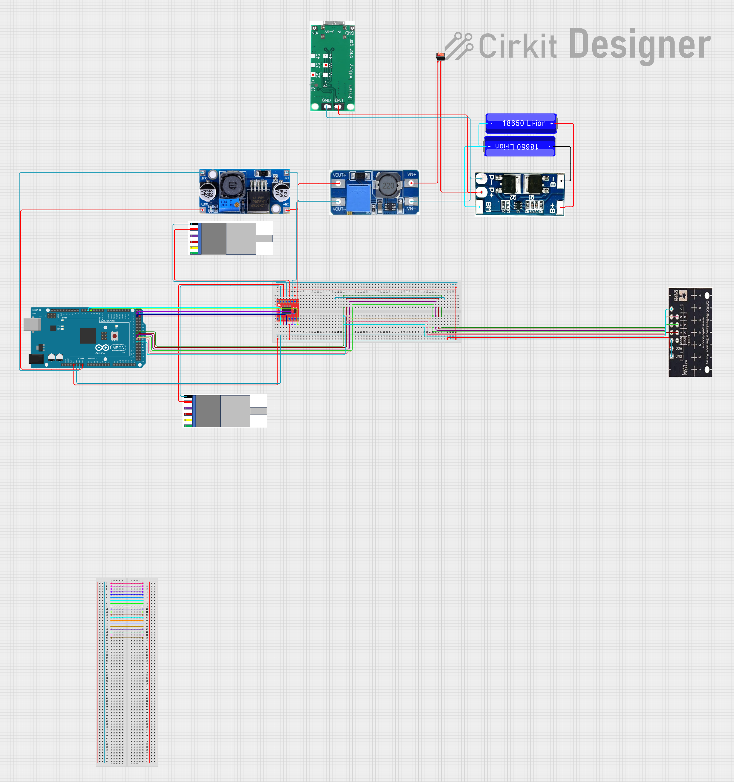
Example: Connecting to an Arduino UNO
Below is an example of how to control the motor using an Arduino UNO and an L298N motor driver.
Circuit Connections
- Connect Terminal 1 and Terminal 2 of the motor to the output pins of the L298N motor driver (e.g., OUT1 and OUT2).
- Connect the L298N's input pins (e.g., IN1 and IN2) to Arduino digital pins (e.g., D9 and D10).
- Connect the L298N's power input to a 6V power supply.
Arduino Code
// Define motor control pins
const int motorPin1 = 9; // IN1 on L298N
const int motorPin2 = 10; // IN2 on L298N

void setup() {
  // Set motor pins as outputs
  pinMode(motorPin1, OUTPUT);
  pinMode(motorPin2, OUTPUT);
}

void loop() {
  // Rotate motor in one direction
  digitalWrite(motorPin1, HIGH);
  digitalWrite(motorPin2, LOW);
  delay(2000); // Run for 2 seconds

  // Stop the motor
  digitalWrite(motorPin1, LOW);
  digitalWrite(motorPin2, LOW);
  delay(1000); // Pause for 1 second

  // Rotate motor in the opposite direction
  digitalWrite(motorPin1, LOW);
  digitalWrite(motorPin2, HIGH);
  delay(2000); // Run for 2 seconds

  // Stop the motor
  digitalWrite(motorPin1, LOW);
  digitalWrite(motorPin2, LOW);
  delay(1000); // Pause for 1 second
}
Troubleshooting and FAQs
Common Issues
Motor Does Not Spin
- Cause: Insufficient power supply or loose connections.
- Solution: Verify that the power supply provides 6V and sufficient current. Check all connections.
Motor Spins in the Wrong Direction
- Cause: Incorrect polarity of the motor terminals.
- Solution: Reverse the connections to the motor terminals.
Motor Overheats
- Cause: Prolonged operation under high load or stall conditions.
- Solution: Reduce the load or limit the motor's runtime. Allow the motor to cool between uses.
Electrical Noise Interference
- Cause: Motor generates electrical noise during operation.
- Solution: Add a 0.1 µF ceramic capacitor across the motor terminals to suppress noise.
FAQs
Q: Can I operate the motor at a voltage higher than 6V?
A: Operating the motor above 6V is not recommended as it may damage the motor or reduce its lifespan.
Q: How do I calculate the torque required for my application?
A: Determine the load's weight and the radius of the wheel or arm. Use the formula:
Torque (N·m) = Force (N) × Radius (m).
Ensure the motor's stall torque exceeds this value.
Q: Can I use this motor without a motor driver?
A: While possible, it is not recommended. A motor driver allows for better control of speed and direction while protecting the motor and power source.
Q: What is the lifespan of this motor?
A: The lifespan depends on operating conditions, such as load, voltage, and runtime. Proper usage and maintenance can significantly extend its life.