How to Use bc547: Examples, Pinouts, and Specs
Introduction
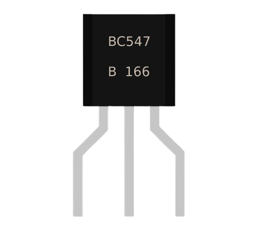
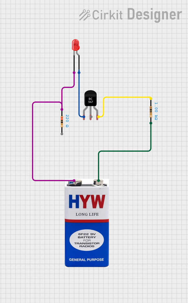
The BC547 transistor is a widely used NPN bipolar junction transistor (BJT) known for its reliability and affordability. It is commonly employed in electronic circuits for amplification and switching applications due to its decent amplification factor and reasonable maximum current handling capability. Typical uses include signal amplification in audio devices, driving small loads, and acting as a switch in various electronic projects, including those involving microcontrollers like the Arduino UNO.
Explore Projects Built with bc547
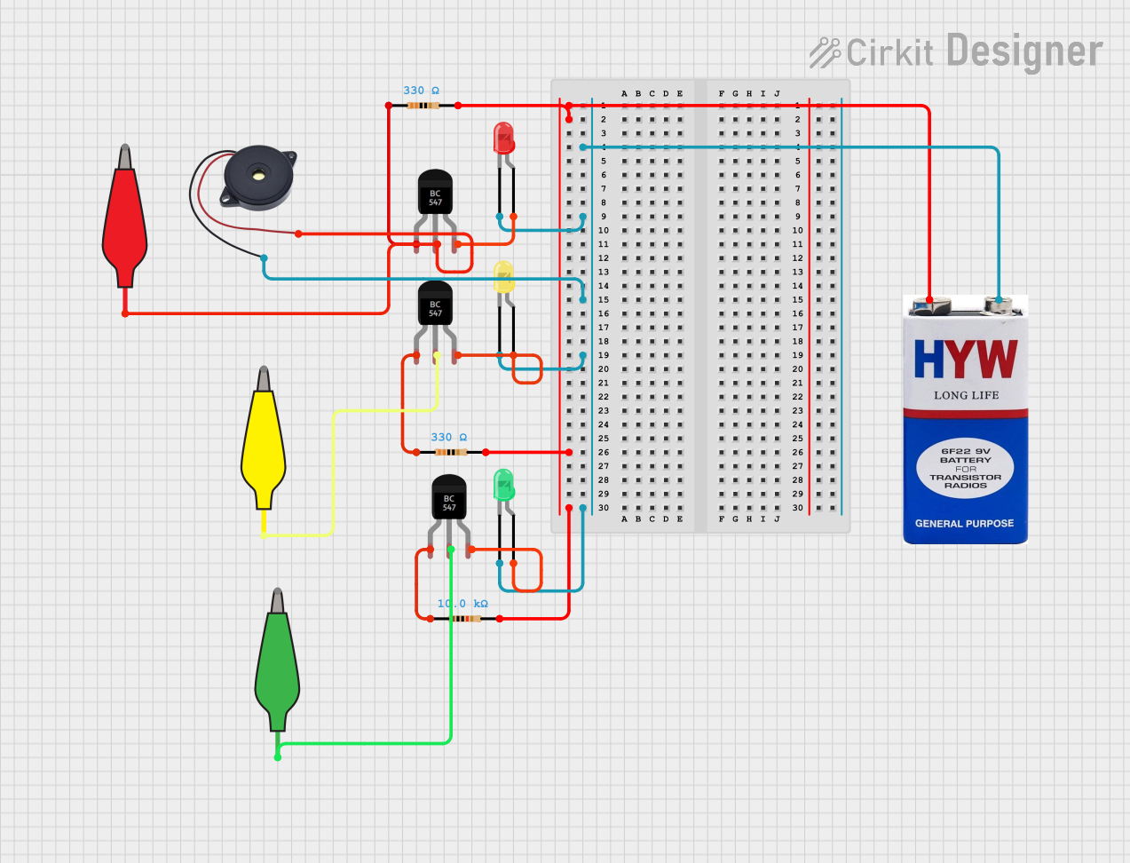
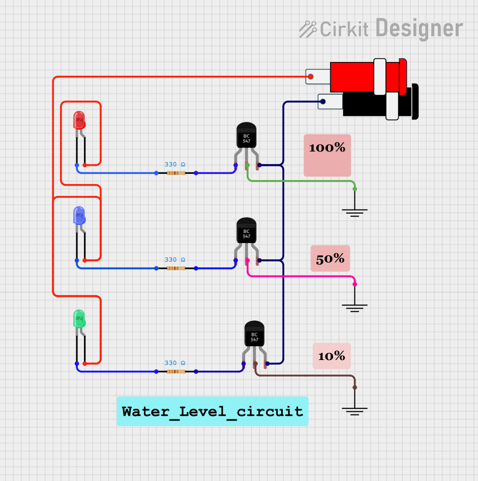
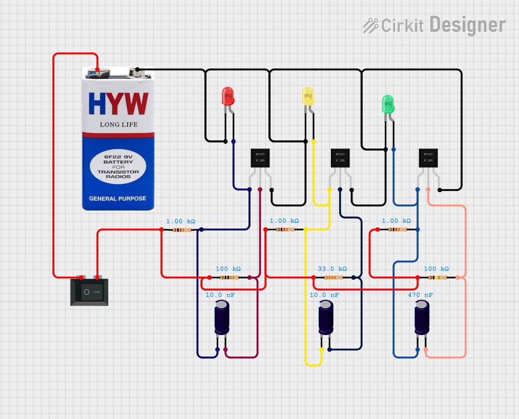
Explore Projects Built with bc547
Technical Specifications
Key Technical Details
- Type: NPN
- Collector-Emitter Voltage (Vce): 45V
- Collector-Base Voltage (Vcb): 50V
- Emitter-Base Voltage (Veb): 6V
- Collector Current (Ic): 100mA
- DC Current Gain (hFE): 110 to 800
- Power Dissipation (Ptot): 625mW
- Transition Frequency (fT): 300MHz
Pin Configuration and Descriptions
| Pin Number | Name | Description |
|---|---|---|
| 1 | Emitter (E) | Emits electrons into the base; must be connected to ground in NPN transistors |
| 2 | Base (B) | Controls the transistor's operation; it is the gate for the majority carriers |
| 3 | Collector (C) | Collects electrons from the base; connected to the load and positive voltage |
Usage Instructions
How to Use the BC547 in a Circuit
- Biasing the Transistor: Ensure that the base-emitter junction is forward-biased and the base-collector junction is reverse-biased for standard operation.
- Base Resistor Selection: Calculate the base resistor value to control the base current, thus regulating the collector current using Ohm's law and the transistor's hFE.
- Load Connection: Connect the load to the collector, ensuring it does not exceed the transistor's maximum current and power ratings.
Important Considerations and Best Practices
- Heat Dissipation: If operating near maximum power dissipation, use a heatsink to prevent overheating.
- Voltage Ratings: Always stay within the specified voltage and current ratings to avoid damaging the transistor.
- Switching Applications: For use as a switch, ensure the transistor is either fully on (saturated) or fully off (cut-off) to minimize power loss.
Example Circuit: BC547 as a Switch with Arduino UNO
// Define the pin connected to the base of the transistor
const int transistorPin = 2;

void setup() {
  // Set the transistor pin as output
  pinMode(transistorPin, OUTPUT);
}

void loop() {
  // Turn on the transistor by applying voltage to the base
  digitalWrite(transistorPin, HIGH);
  delay(1000); // Wait for 1 second

  // Turn off the transistor by removing voltage from the base
  digitalWrite(transistorPin, LOW);
  delay(1000); // Wait for 1 second
}
Note: Ensure a suitable base resistor is in series with the transistorPin to limit the base current.
Troubleshooting and FAQs
Common Issues
- Transistor Not Switching: Check if the base resistor is of the correct value and the base is receiving enough current.
- Overheating: Ensure the power dissipation is within limits and consider using a heatsink.
- Unexpected Operation: Verify that the pin configuration is correct and that the transistor is not installed backward.
Solutions and Tips
- Base Resistor Calculation: Use the formula
Rb = (Vio - Vbe) / Ib, whereViois the input voltage from the Arduino,Vbeis the base-emitter voltage (typically 0.7V for silicon transistors), andIbis the desired base current. - Heat Management: Attach a heatsink if the transistor gets too hot to the touch during operation.
- Testing Transistor: Use a multimeter to check for junction continuity and ensure the transistor is functioning correctly.
FAQs
Q: Can I use the BC547 to drive a motor? A: Yes, but only if the motor's current requirements do not exceed the BC547's maximum collector current rating.
Q: What can I do if the BC547 is not providing enough current? A: Consider using a transistor with a higher current rating or using the BC547 to drive a power transistor that can handle the required current.
Q: How do I know if my BC547 is damaged? A: A damaged BC547 may show a short circuit or open circuit when measuring with a multimeter, or it may not respond to base current changes.