
How to Use JST XH 4P Female: Examples, Pinouts, and Specs
 Design with JST XH 4P Female in Cirkit Designer
Introduction
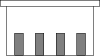
The JST XH 4P Female connector is a 4-pin female connector widely used in electronic circuits for connecting wires. It features a compact design and a reliable locking mechanism, ensuring secure and stable connections. This connector is part of the JST XH series, known for its durability and ease of use. It is commonly used in applications such as battery connections, PCB interfaces, and small electronic devices.
Explore Projects Built with JST XH 4P Female
 Open Project in Cirkit Designer
 Open Project in Cirkit Designer
 Open Project in Cirkit Designer
 Open Project in Cirkit Designer
Explore Projects Built with JST XH 4P Female
Open Project in Cirkit DesignerOpen Project in Cirkit DesignerOpen Project in Cirkit DesignerOpen Project in Cirkit DesignerCommon Applications:
- Battery pack connections in RC models and drones
- PCB-to-wire connections in consumer electronics
- Power and signal transmission in small devices
- Prototyping and DIY electronics projects
Technical Specifications
Key Technical Details:
- Connector Type: JST XH 4P Female
- Number of Pins: 4
- Pitch (Pin Spacing): 2.5 mm
- Rated Voltage: 250V AC/DC
- Rated Current: 3A (maximum)
- Contact Resistance: ≤ 20 mΩ
- Insulation Resistance: ≥ 1000 MΩ
- Operating Temperature Range: -25°C to +85°C
- Material:
- Housing: Nylon 66 (UL94V-0 flame-retardant)
- Contacts: Phosphor bronze with tin plating
Pin Configuration and Descriptions:
The JST XH 4P Female connector has four pins arranged in a single row with a 2.5 mm pitch. Below is the pin configuration:
| Pin Number | Description | Typical Use |
|---|---|---|
| 1 | VCC (Power Supply) | Positive voltage input |
| 2 | GND (Ground) | Ground connection |
| 3 | Signal/Data Line 1 | Data or signal transmission line |
| 4 | Signal/Data Line 2 | Data or signal transmission line |
Note: The pin assignments may vary depending on the specific application. Always refer to the circuit design or datasheet for proper wiring.
Usage Instructions
How to Use the JST XH 4P Female Connector:
Wire Preparation:
- Strip approximately 2-3 mm of insulation from the end of each wire.
- Use a crimping tool to attach JST XH-compatible crimp terminals to the wires.
Inserting Wires:
- Insert the crimped terminals into the connector housing until they click into place.
- Ensure the terminals are fully seated and locked to prevent loose connections.
Connecting to a Male Header:
- Align the JST XH 4P Female connector with the corresponding male header.
- Push the connector gently until the locking mechanism clicks, ensuring a secure connection.
Mounting on a PCB:
- If using a PCB-mounted male header, solder the male header to the PCB before connecting the female connector.
Important Considerations:
- Avoid Overcurrent: Do not exceed the rated current of 3A to prevent overheating or damage.
- Secure Connections: Ensure the locking mechanism is engaged to avoid accidental disconnections.
- Proper Orientation: Verify the orientation of the connector to avoid reversing polarity or miswiring.
- Environmental Conditions: Use the connector within the specified temperature range (-25°C to +85°C).
Example: Connecting to an Arduino UNO
The JST XH 4P Female connector can be used to connect sensors or modules to an Arduino UNO. Below is an example of wiring and code for reading data from a sensor connected via the JST XH 4P Female connector.
Wiring:
- Pin 1 (VCC) → Arduino 5V
- Pin 2 (GND) → Arduino GND
- Pin 3 (Signal/Data Line 1) → Arduino Analog Pin A0
- Pin 4 (Signal/Data Line 2) → Arduino Analog Pin A1 (if needed)
Arduino Code:
// Example code for reading data from a sensor connected via JST XH 4P Female
const int sensorPin1 = A0; // Pin connected to Signal/Data Line 1
const int sensorPin2 = A1; // Pin connected to Signal/Data Line 2 (optional)

void setup() {
  Serial.begin(9600); // Initialize serial communication at 9600 baud
  pinMode(sensorPin1, INPUT); // Set Signal/Data Line 1 as input
  pinMode(sensorPin2, INPUT); // Set Signal/Data Line 2 as input (if used)
}

void loop() {
  int sensorValue1 = analogRead(sensorPin1); // Read value from Signal/Data Line 1
  int sensorValue2 = analogRead(sensorPin2); // Read value from Signal/Data Line 2

  // Print the sensor values to the Serial Monitor
  Serial.print("Sensor 1 Value: ");
  Serial.println(sensorValue1);
  Serial.print("Sensor 2 Value: ");
  Serial.println(sensorValue2);

  delay(1000); // Wait for 1 second before reading again
}
Note: Modify the code as needed based on the specific sensor or module being used.
Troubleshooting and FAQs
Common Issues:
Loose Connections:
- Cause: Terminals not fully inserted into the connector housing.
- Solution: Reinsert the terminals until they click into place.
Overheating:
- Cause: Exceeding the rated current of 3A.
- Solution: Ensure the current does not exceed the specified limit.
Reversed Polarity:
- Cause: Incorrect wiring of VCC and GND pins.
- Solution: Double-check the pin configuration and wiring before powering the circuit.
Intermittent Signal Loss:
- Cause: Poor crimping of terminals or loose connections.
- Solution: Use a proper crimping tool and verify the terminals are securely attached.
FAQs:
Q1: Can the JST XH 4P Female connector handle high-frequency signals?
A1: Yes, the connector can handle high-frequency signals, but ensure proper shielding and grounding in your circuit to minimize interference.
Q2: Is the JST XH 4P Female connector compatible with other JST series connectors?
A2: No, the JST XH 4P Female connector is specifically designed for the XH series and may not be compatible with other JST series due to differences in pitch and design.
Q3: Can I use this connector for power delivery?
A3: Yes, the connector can handle up to 3A of current, making it suitable for low-power applications.
Q4: How do I remove a wire from the connector housing?
A4: Use a small flathead screwdriver or a pin to gently release the locking tab on the terminal, then pull the wire out carefully.
By following this documentation, you can effectively use the JST XH 4P Female connector in your electronic projects.