How to Use Lora RYLR998: Examples, Pinouts, and Specs
Introduction
The Lora RYLR998, manufactured by REYAX, is a low-power, long-range wireless transceiver module that operates on the LoRa (Long Range) protocol. It is specifically designed for Internet of Things (IoT) applications, enabling communication over distances of several kilometers with minimal power consumption. The module is ideal for applications requiring reliable, long-range data transmission, such as remote sensor monitoring, smart agriculture, industrial automation, and smart cities.
Explore Projects Built with Lora RYLR998


Explore Projects Built with Lora RYLR998
Common Applications
- Remote sensor data transmission
- Smart agriculture and environmental monitoring
- Industrial automation and control
- Smart metering and utilities
- Asset tracking and geolocation
- Home automation and security systems
Technical Specifications
The Lora RYLR998 module is built to deliver robust performance in a compact form factor. Below are its key technical specifications:
| Parameter | Specification |
|---|---|
| Operating Voltage | 2.8V to 3.6V |
| Operating Current | 10.5mA (transmit), 0.5µA (sleep mode) |
| Frequency Range | 868MHz / 915MHz |
| Modulation Technique | LoRa (Long Range) |
| Communication Range | Up to 15 km (line of sight) |
| Data Rate | 0.3 kbps to 37.5 kbps |
| Interface | UART (3.3V logic level) |
| Operating Temperature | -40°C to +85°C |
| Dimensions | 25mm x 15mm x 2.2mm |
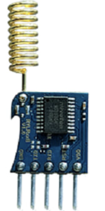
Pin Configuration and Descriptions
The RYLR998 module has 8 pins, as described in the table below:
| Pin Number | Pin Name | Description |
|---|---|---|
| 1 | VCC | Power supply input (2.8V to 3.6V) |
| 2 | GND | Ground |
| 3 | TXD | UART Transmit Data (3.3V logic level) |
| 4 | RXD | UART Receive Data (3.3V logic level) |
| 5 | RESET | Module reset (active low) |
| 6 | NC | Not connected |
| 7 | ANT | Antenna connection |
| 8 | NC | Not connected |
Usage Instructions
The Lora RYLR998 module is straightforward to integrate into IoT projects. Below are the steps and best practices for using the module:
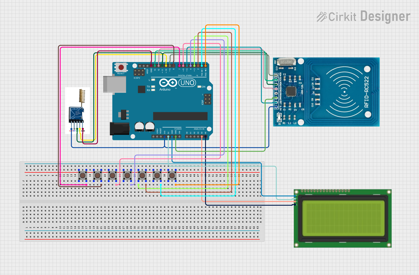
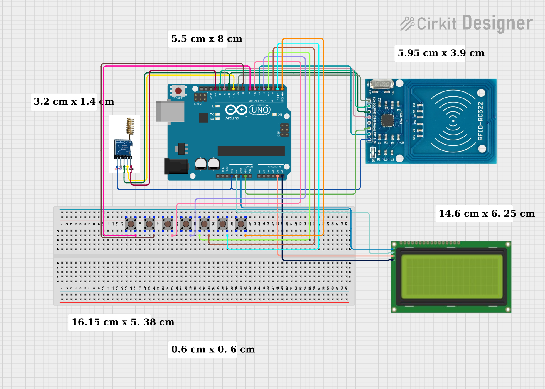
Connecting the Module
- Power Supply: Connect the VCC pin to a 3.3V power source and the GND pin to ground.
- UART Communication: Connect the TXD pin of the module to the RX pin of your microcontroller (e.g., Arduino UNO) and the RXD pin of the module to the TX pin of the microcontroller.
- Antenna: Attach a suitable antenna to the ANT pin for optimal signal transmission and reception.
- Reset: Optionally, connect the RESET pin to a GPIO pin on your microcontroller for manual or software-controlled resets.
Example Code for Arduino UNO
Below is an example of how to use the RYLR998 module with an Arduino UNO for basic communication:
#include <SoftwareSerial.h>

// Define RX and TX pins for SoftwareSerial
SoftwareSerial loraSerial(10, 11); // RX = Pin 10, TX = Pin 11

void setup() {
  // Initialize serial communication with the Lora module
  loraSerial.begin(9600); // Default baud rate for RYLR998
  Serial.begin(9600);     // Serial monitor communication

  // Send initialization command to the Lora module
  loraSerial.println("AT+ADDRESS=1"); // Set device address to 1
  delay(100);
  loraSerial.println("AT+NETWORKID=5"); // Set network ID to 5
  delay(100);
  loraSerial.println("AT+BAND=915000000"); // Set frequency to 915 MHz
  delay(100);

  Serial.println("Lora module initialized.");
}

void loop() {
  // Send a message via the Lora module
  loraSerial.println("AT+SEND=2,5,Hello");
  // Send "Hello" to device address 2 with 5 bytes of data
  delay(2000);

  // Check for incoming messages
  if (loraSerial.available()) {
    String message = loraSerial.readString();
    Serial.println("Received: " + message);
  }
}
Important Considerations
- Power Supply: Ensure a stable 3.3V power source to avoid damage to the module.
- Antenna: Use a high-quality antenna to maximize communication range and reliability.
- UART Logic Levels: The RYLR998 operates at 3.3V logic levels. If using a 5V microcontroller, use a level shifter to prevent damage.
- Command Set: Familiarize yourself with the AT command set provided in the RYLR998 datasheet for advanced configuration.
Troubleshooting and FAQs
Common Issues and Solutions
No Response from the Module
- Cause: Incorrect wiring or baud rate mismatch.
- Solution: Double-check the connections and ensure the baud rate is set to 9600.
Limited Communication Range
- Cause: Poor antenna quality or obstructions in the signal path.
- Solution: Use a high-gain antenna and ensure a clear line of sight between devices.
Module Not Initializing
- Cause: Insufficient power supply or incorrect AT commands.
- Solution: Verify the power supply voltage and check the AT command syntax.
Data Loss or Corruption
- Cause: Interference or incorrect UART settings.
- Solution: Reduce interference sources and ensure UART settings match between devices.
FAQs
Q: Can the RYLR998 module communicate with other LoRa devices?
A: Yes, as long as the devices are configured with the same frequency, network ID, and data rate.
Q: What is the maximum range of the RYLR998?
A: The module can achieve up to 15 km in line-of-sight conditions. However, range may vary based on environmental factors.
Q: Does the module support encryption?
A: Yes, the RYLR998 supports AES-128 encryption for secure communication.
Q: Can I use the module with a 5V microcontroller?
A: Yes, but you must use a level shifter to convert the 5V logic levels to 3.3V.
By following this documentation, users can effectively integrate the Lora RYLR998 module into their IoT projects and achieve reliable long-range communication.