How to Use LORA_01H: Examples, Pinouts, and Specs
Introduction
The LORA_01H is a versatile and powerful LoRa (Long Range) module designed for wireless communication over long distances. Operating in the 868-915 MHz frequency range, this module is particularly suitable for Internet of Things (IoT) applications, such as remote sensing, home automation, and telemetry. Its long-range capabilities, coupled with low power consumption, make it an excellent choice for projects where connectivity is crucial, but power resources are limited.
Explore Projects Built with LORA_01H

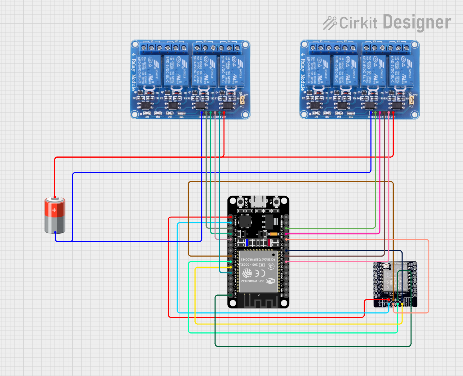
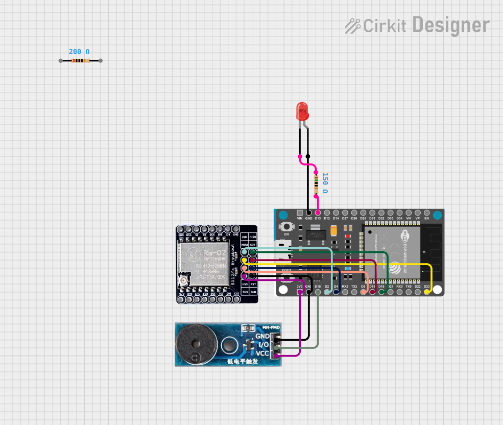
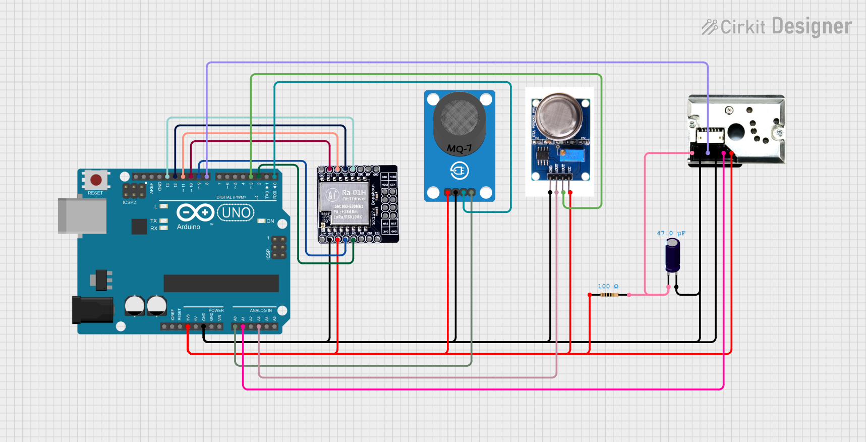
Explore Projects Built with LORA_01H
Common Applications and Use Cases
- Remote environmental monitoring
- Smart agriculture
- Asset tracking
- Home and industrial automation
- Smart city infrastructure
- Wireless alarm and security systems
Technical Specifications
Key Technical Details
| Parameter | Specification |
|---|---|
| Frequency Range | 868-915 MHz |
| Modulation | LoRa Spread Spectrum |
| Output Power | +20 dBm - 100 mW nominal |
| Sensitivity | -148 dBm minimum |
| Supply Voltage | 3.3V - 5.5V DC |
| Operating Current | 120 mA (transmit), 10 mA (idle) |
| Interface | SPI |
| Operating Temperature | -40°C to +85°C |
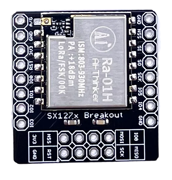
Pin Configuration and Descriptions
| Pin Number | Name | Description |
|---|---|---|
| 1 | VCC | Power supply (3.3V - 5.5V DC) |
| 2 | GND | Ground |
| 3 | SCK | SPI Clock |
| 4 | MISO | Master In Slave Out (SPI Data Output) |
| 5 | MOSI | Master Out Slave In (SPI Data Input) |
| 6 | NSS | SPI Chip Select (Active Low) |
| 7 | DIO0 | Digital I/O (used for interrupt signaling) |
| 8 | RST | Reset (Active Low) |
Usage Instructions
How to Use the Component in a Circuit
- Power Supply: Connect the VCC pin to a 3.3V - 5.5V DC power source and the GND pin to the ground of your circuit.
- SPI Interface: Connect the SCK, MISO, MOSI, and NSS pins to the corresponding SPI pins on your microcontroller (e.g., Arduino UNO).
- Interrupts: Connect the DIO0 pin to an interrupt-capable GPIO pin on your microcontroller to handle events such as packet reception.
- Reset: The RST pin can be connected to a GPIO pin for software reset functionality.
Important Considerations and Best Practices
- Ensure that the power supply is clean and within the specified voltage range to prevent damage.
- Use proper decoupling capacitors close to the module's power supply pins to minimize power supply noise.
- Keep the antenna area clear of metal objects to avoid interference with the RF signal.
- Follow local regulations regarding the use of RF frequencies and power levels.
Example Code for Arduino UNO
#include <SPI.h>
#include <LoRa.h>

// Define the LoRa module pins
#define SS_PIN   10
#define RST_PIN  9
#define DIO0_PIN 2

void setup() {
  // Initialize LoRa module
  LoRa.setPins(SS_PIN, RST_PIN, DIO0_PIN);
  if (!LoRa.begin(915E6)) { // Initialize LoRa at 915 MHz
    Serial.println("Starting LoRa failed!");
    while (1);
  }
}

void loop() {
  // Send a message
  LoRa.beginPacket();
  LoRa.print("Hello, LoRa!");
  LoRa.endPacket();

  // Wait for a short interval before sending the next message
  delay(2000);
}
Troubleshooting and FAQs
Common Issues Users Might Face
- No Communication: Ensure that the SPI connections are correct and that the module is properly powered.
- Short Range: Check the antenna connections and ensure there are no obstructions or interference sources nearby.
- Intermittent Operation: Verify that the power supply is stable and that the module is not overheating.
Solutions and Tips for Troubleshooting
- Double-check wiring, especially the SPI and power connections.
- Use an oscilloscope to verify the SPI signals if communication issues persist.
- Ensure that the antenna is properly tuned for the operating frequency.
FAQs
Q: Can I use the LORA_01H module with a 5V microcontroller like the Arduino UNO? A: Yes, but ensure that the logic level for the SPI interface is shifted down to 3.3V to avoid damaging the module.
Q: How can I increase the range of the LORA_01H module? A: Use a high-quality antenna, minimize obstructions, and ensure that the module is configured for maximum transmit power and sensitivity.
Q: What is the maximum data rate of the LORA_01H module? A: The data rate can vary depending on the spreading factor and bandwidth settings, but it typically ranges from 0.3 kbps to 27 kbps.
Q: Is the LORA_01H module compatible with other LoRa devices? A: Yes, it is compatible with other LoRa devices as long as they operate on the same frequency and use compatible settings.