How to Use 1-kanaals 3V relais module: Examples, Pinouts, and Specs
Introduction
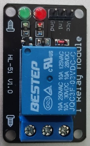
The 1-kanaals 3V relais module by Kiwi is a single-channel relay module designed to operate at a low voltage of 3V. This module is ideal for controlling high-voltage devices using low-voltage signals, making it a versatile component in automation and control systems. It acts as an electrically operated switch, allowing microcontrollers or other low-power devices to safely control high-power circuits.
Explore Projects Built with 1-kanaals 3V relais module


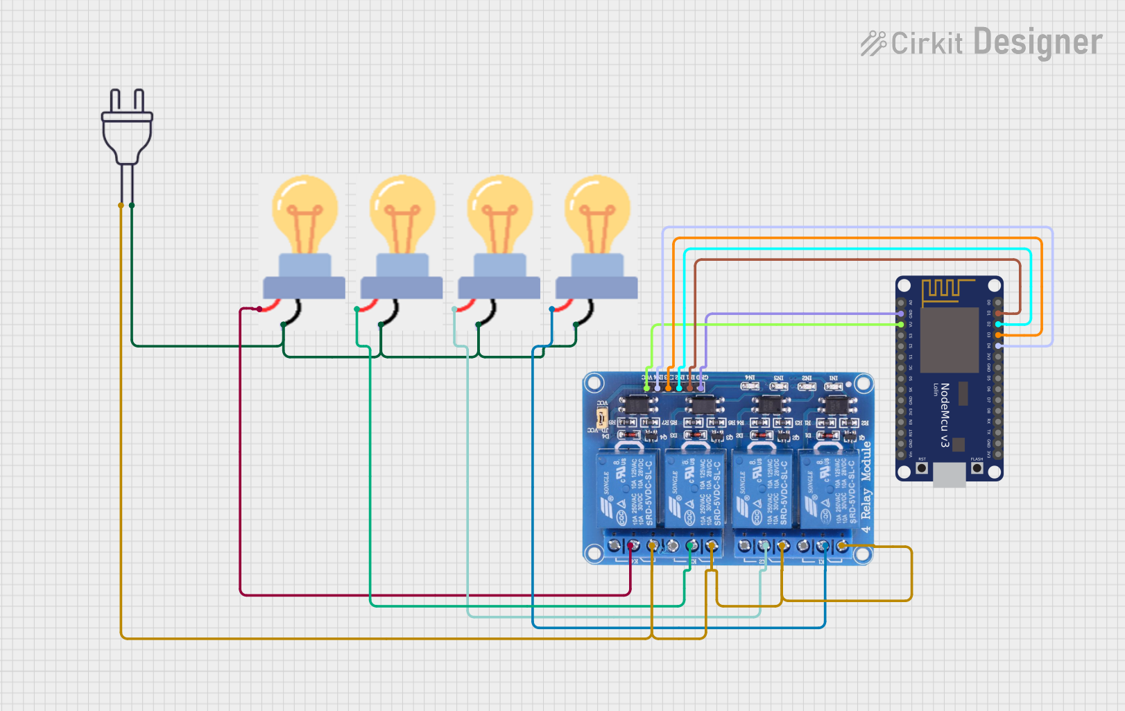
Explore Projects Built with 1-kanaals 3V relais module
Common Applications and Use Cases
- Home automation systems (e.g., controlling lights, fans, or appliances)
- Industrial control systems
- Robotics and IoT projects
- Motor and pump control
- Signal isolation between low-power and high-power circuits
Technical Specifications
The following table outlines the key technical details of the 1-kanaals 3V relais module:
| Parameter | Specification |
|---|---|
| Operating Voltage | 3V DC |
| Trigger Voltage | 2.7V to 3.3V DC |
| Maximum Load Voltage | 250V AC / 30V DC |
| Maximum Load Current | 10A |
| Relay Type | SPDT (Single Pole Double Throw) |
| Isolation | Optocoupler isolation for safety |
| Dimensions | 50mm x 26mm x 18mm |
| Weight | ~15g |
Pin Configuration and Descriptions
The module has a total of 6 pins and terminals, as described below:
Input Pins (Low Voltage Side)
| Pin | Name | Description |
|---|---|---|
| 1 | VCC | Connect to a 3V DC power supply (positive terminal). |
| 2 | GND | Connect to the ground of the power supply. |
| 3 | IN | Signal input pin. A HIGH signal activates the relay, and a LOW signal deactivates it. |
Output Terminals (High Voltage Side)
| Terminal | Name | Description |
|---|---|---|
| 1 | COM | Common terminal for the relay switch. |
| 2 | NO | Normally Open terminal. Connect the load here if you want it to be OFF by default. |
| 3 | NC | Normally Closed terminal. Connect the load here if you want it to be ON by default. |
Usage Instructions
How to Use the Component in a Circuit
- Power the Module: Connect the VCC pin to a 3V DC power supply and the GND pin to the ground.
- Control Signal: Connect the IN pin to a microcontroller (e.g., Arduino UNO) or any other control circuit. A HIGH signal (3V) will activate the relay, while a LOW signal (0V) will deactivate it.
- Connect the Load:
- For devices that should be OFF by default, connect the load between the COM and NO terminals.
- For devices that should be ON by default, connect the load between the COM and NC terminals.
- Isolation: Ensure proper isolation between the low-voltage control side and the high-voltage load side to prevent damage or hazards.
Important Considerations and Best Practices
- Current Ratings: Ensure the load does not exceed the relay's maximum current rating of 10A.
- Flyback Diode: If controlling an inductive load (e.g., motors), use a flyback diode across the load to protect the relay from voltage spikes.
- Safety: Always handle high-voltage connections with care. Disconnect power before making any changes to the circuit.
- Signal Stability: Use a pull-down resistor on the IN pin to prevent false triggering due to noise.
Example: Connecting to an Arduino UNO
Below is an example of how to control the relay module using an Arduino UNO:
Circuit Connections
- Connect the VCC pin of the relay module to the 3.3V pin of the Arduino.
- Connect the GND pin of the relay module to the GND pin of the Arduino.
- Connect the IN pin of the relay module to digital pin 7 of the Arduino.
- Connect a load (e.g., a light bulb) between the COM and NO terminals of the relay.
Arduino Code
// Define the relay control pin
const int relayPin = 7;

void setup() {
  // Set the relay pin as an output
  pinMode(relayPin, OUTPUT);

  // Ensure the relay is off at startup
  digitalWrite(relayPin, LOW);
}

void loop() {
  // Turn the relay ON
  digitalWrite(relayPin, HIGH);
  delay(5000); // Keep the relay ON for 5 seconds

  // Turn the relay OFF
  digitalWrite(relayPin, LOW);
  delay(5000); // Keep the relay OFF for 5 seconds
}
Troubleshooting and FAQs
Common Issues and Solutions
Relay Not Activating:
- Cause: Insufficient voltage or current to the VCC pin.
- Solution: Ensure the power supply provides a stable 3V DC and sufficient current.
False Triggering:
- Cause: Electrical noise or floating IN pin.
- Solution: Use a pull-down resistor (e.g., 10kΩ) on the IN pin to stabilize the signal.
Load Not Switching:
- Cause: Incorrect wiring of the load to the relay terminals.
- Solution: Double-check the connections to the COM, NO, and NC terminals.
Overheating:
- Cause: Load exceeds the relay's maximum current rating.
- Solution: Use a load within the specified 10A limit or use a higher-rated relay.
FAQs
Q1: Can I use this relay module with a 5V microcontroller?
A1: Yes, but you will need a level shifter or resistor divider to step down the control signal to 3V.
Q2: Is the relay module safe for switching AC loads?
A2: Yes, it can handle up to 250V AC, but ensure proper insulation and safety precautions.
Q3: Can I control multiple relays with one microcontroller?
A3: Yes, as long as each relay has its own control pin and the microcontroller can supply sufficient current.
Q4: What is the purpose of the optocoupler?
A4: The optocoupler provides electrical isolation between the low-voltage control circuit and the high-voltage load circuit, enhancing safety.