
How to Use ZXLD1360: Examples, Pinouts, and Specs
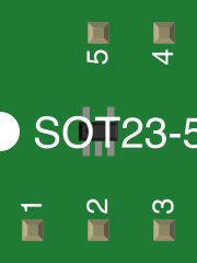
 Design with ZXLD1360 in Cirkit Designer
Introduction
The ZXLD1360 is a high-efficiency, non-synchronous step-down (buck) LED driver designed for driving high-brightness LEDs. It provides a constant current output, ensuring stable and reliable LED operation. With an adjustable output current and a wide input voltage range (7V to 30V), the ZXLD1360 is ideal for a variety of lighting applications, including automotive lighting, architectural lighting, and general-purpose LED illumination.
Explore Projects Built with ZXLD1360
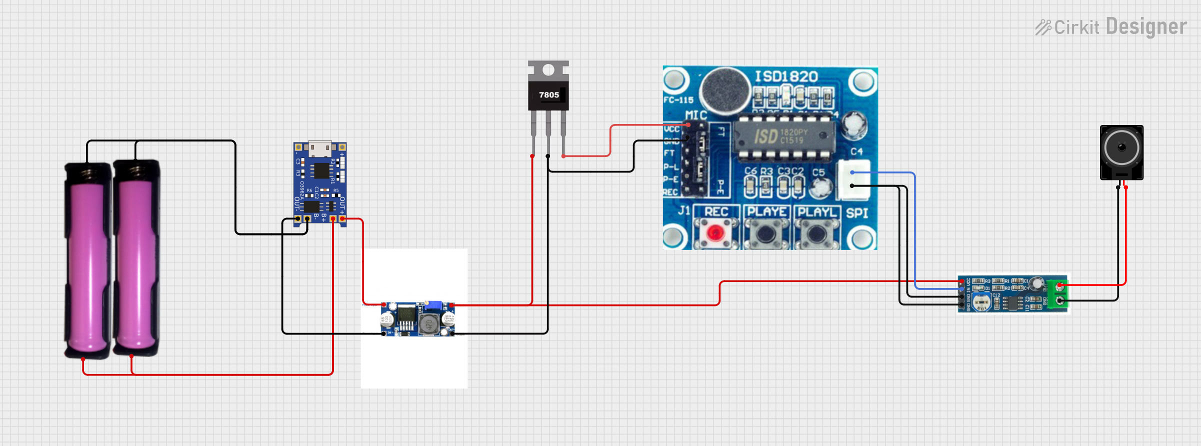 Open Project in Cirkit Designer
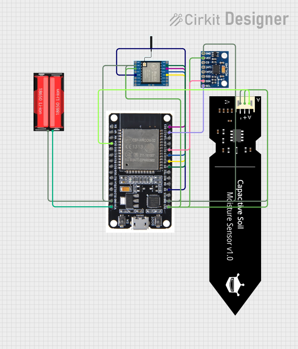 Open Project in Cirkit Designer
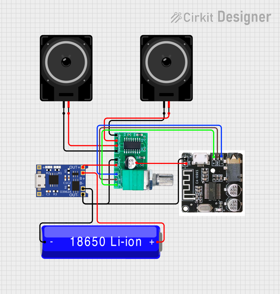 Open Project in Cirkit Designer
 Open Project in Cirkit Designer
Explore Projects Built with ZXLD1360
Open Project in Cirkit DesignerOpen Project in Cirkit DesignerOpen Project in Cirkit DesignerOpen Project in Cirkit DesignerCommon Applications
- Automotive lighting systems
- LED backlighting for displays
- Architectural and decorative lighting
- General-purpose high-brightness LED illumination
- Solar-powered LED systems
Technical Specifications
Key Technical Details
| Parameter | Value |
|---|---|
| Input Voltage Range | 7V to 30V |
| Output Current Range | Adjustable up to 1A |
| Efficiency | Up to 95% |
| Switching Frequency | 400kHz (typical) |
| LED Current Accuracy | ±5% |
| Operating Temperature Range | -40°C to +85°C |
| Package Type | TSOT23-5 |
Pin Configuration and Descriptions
The ZXLD1360 is available in a TSOT23-5 package with the following pinout:
| Pin Number | Pin Name | Description |
|---|---|---|
| 1 | VIN | Input voltage pin. Connect to the power supply (7V to 30V). |
| 2 | GND | Ground pin. Connect to the circuit ground. |
| 3 | ISENSE | Current sense pin. Connect to the sense resistor to set the LED current. |
| 4 | ADJ | Adjustment pin. Used for dimming control or setting the output current. |
| 5 | LX | Switching node. Connect to the inductor and LED cathode. |
Usage Instructions
How to Use the ZXLD1360 in a Circuit
- Power Supply: Connect a DC power supply (7V to 30V) to the VIN pin. Ensure the supply voltage matches the requirements of your LEDs.
- LED Connection: Connect the LED anode to the power supply and the cathode to the LX pin.
- Current Setting: Use a sense resistor (RSENSE) between the ISENSE pin and ground to set the LED current. The current is determined by the formula: [ I_{LED} = \frac{0.1}{R_{SENSE}} ] For example, to set the LED current to 500mA, use a 0.2Ω resistor.
- Dimming Control: Apply a PWM signal (0.3V to 2.5V) or a DC voltage to the ADJ pin for dimming. A higher voltage increases the LED current.
- Inductor Selection: Choose an inductor with a suitable current rating and low DC resistance to ensure efficient operation.
Important Considerations
- Use low-ESR capacitors for input and output filtering to minimize noise.
- Ensure proper thermal management, as high-power LEDs can generate significant heat.
- Avoid exceeding the maximum input voltage (30V) to prevent damage to the device.
- For optimal performance, place the sense resistor and other critical components close to the IC.
Example: Connecting the ZXLD1360 to an Arduino UNO
The ZXLD1360 can be controlled using an Arduino UNO for PWM dimming. Below is an example code snippet:
// Example code to control the ZXLD1360 LED driver using Arduino UNO
// This code generates a PWM signal on pin 9 to adjust LED brightness.

const int pwmPin = 9; // PWM output pin connected to the ADJ pin of ZXLD1360

void setup() {
  pinMode(pwmPin, OUTPUT); // Set pin 9 as an output
}

void loop() {
  // Gradually increase brightness
  for (int dutyCycle = 0; dutyCycle <= 255; dutyCycle++) {
    analogWrite(pwmPin, dutyCycle); // Write PWM signal to ADJ pin
    delay(10); // Delay for smooth brightness transition
  }

  // Gradually decrease brightness
  for (int dutyCycle = 255; dutyCycle >= 0; dutyCycle--) {
    analogWrite(pwmPin, dutyCycle); // Write PWM signal to ADJ pin
    delay(10); // Delay for smooth brightness transition
  }
}
Troubleshooting and FAQs
Common Issues and Solutions
LEDs Not Lighting Up
- Cause: Incorrect wiring or insufficient input voltage.
- Solution: Verify all connections and ensure the input voltage is within the specified range.
Flickering LEDs
- Cause: Poor filtering or unstable power supply.
- Solution: Add low-ESR capacitors to the input and output for better filtering.
Overheating
- Cause: Excessive current or inadequate thermal management.
- Solution: Check the sense resistor value and ensure proper heat dissipation using heatsinks or thermal vias.
Dimming Not Working
- Cause: Incorrect PWM signal or ADJ pin voltage.
- Solution: Verify the PWM signal frequency and amplitude. Ensure the ADJ pin voltage is within the 0.3V to 2.5V range.
FAQs
Q: Can the ZXLD1360 drive multiple LEDs in series?
A: Yes, as long as the total forward voltage of the LEDs does not exceed the input voltage minus the dropout voltage.
Q: What is the maximum LED current the ZXLD1360 can handle?
A: The ZXLD1360 can handle up to 1A of LED current, depending on the sense resistor value and thermal conditions.
Q: Is it possible to use the ZXLD1360 for battery-powered applications?
A: Yes, the wide input voltage range makes it suitable for battery-powered systems, provided the battery voltage is within 7V to 30V.
Q: What type of inductor should I use with the ZXLD1360?
A: Use an inductor with a current rating higher than the LED current and low DC resistance for optimal efficiency.