How to Use WS2812B-8x32: Examples, Pinouts, and Specs
Introduction
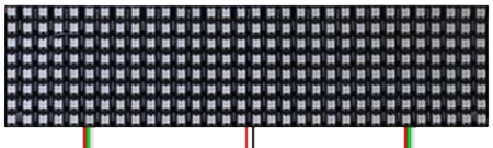
The WS2812B-8x32 is a flexible LED matrix display consisting of 256 individually addressable RGB LEDs arranged in an 8x32 grid. Each LED in the matrix is based on the WS2812B smart RGB LED, which integrates a control circuit and RGB chip into a single package. This component is widely used for creating colorful lighting effects, animations, and visual displays in projects such as decorative lighting, signage, and interactive installations.
Explore Projects Built with WS2812B-8x32

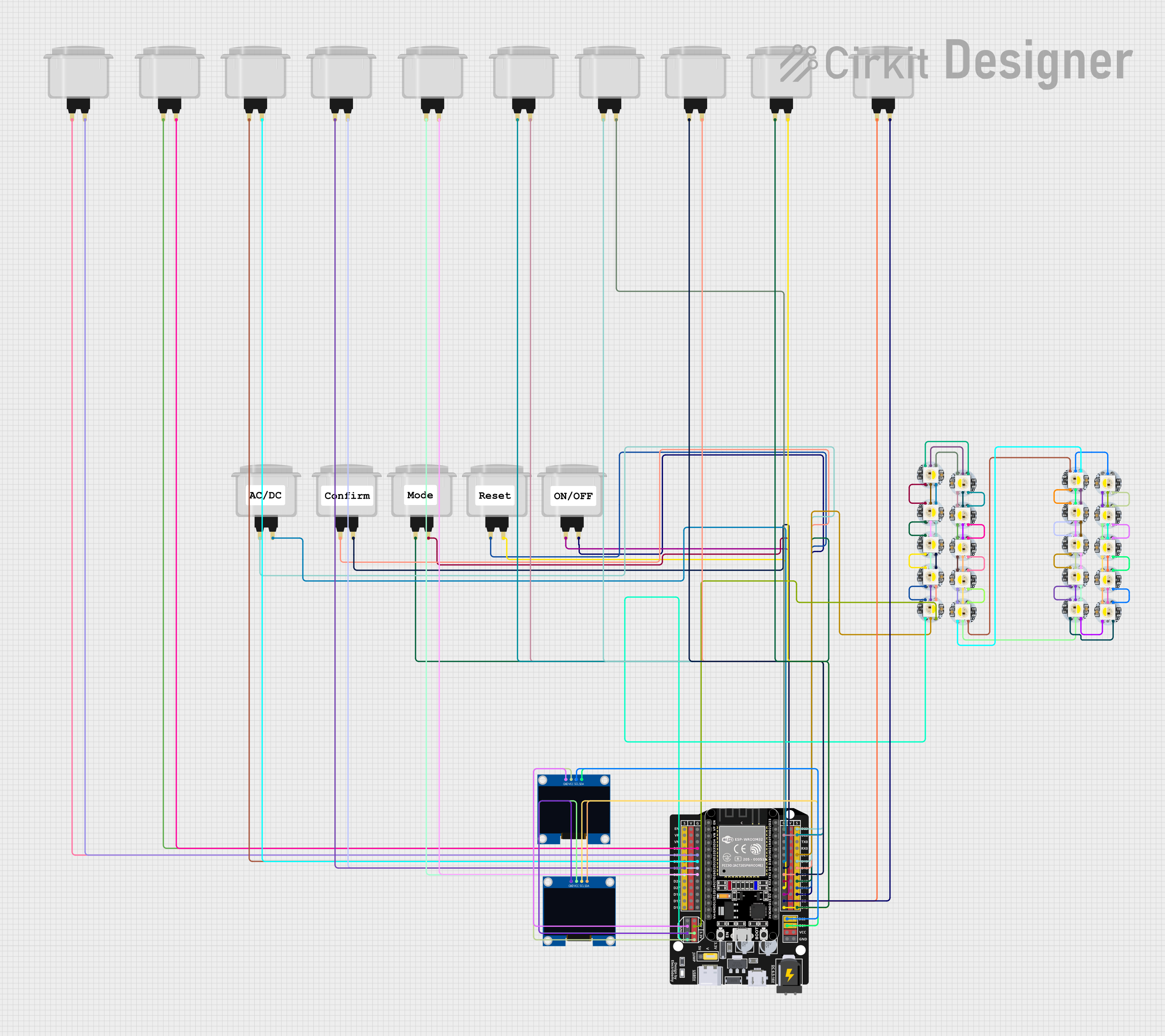
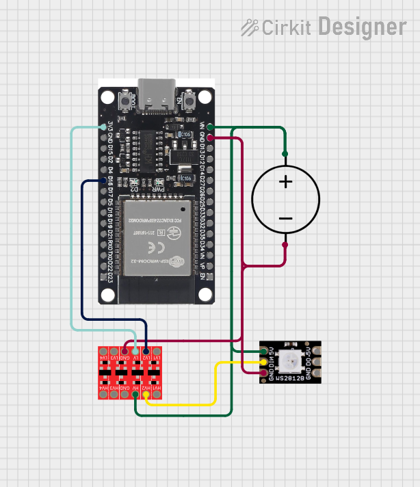

Explore Projects Built with WS2812B-8x32
Common Applications
- Decorative lighting for events and installations
- Animated signage and displays
- Interactive art projects
- DIY projects and prototyping
- Gaming setups and PC case lighting
Technical Specifications
The WS2812B-8x32 LED matrix has the following key technical specifications:
| Parameter | Value |
|---|---|
| LED Type | WS2812B RGB LEDs |
| Matrix Dimensions | 8 rows x 32 columns (256 LEDs) |
| Operating Voltage | 5V DC |
| Power Consumption | ~60mA per LED at full brightness |
| Communication Protocol | Single-wire serial (data input) |
| LED Color Depth | 24-bit (8 bits per color channel) |
| Refresh Rate | ~400 Hz |
| Dimensions | ~320mm x 80mm |
| Flexible PCB | Yes |
Pin Configuration
The WS2812B-8x32 matrix has three main pins for operation:
| Pin Name | Description |
|---|---|
| VCC | Power supply input (5V DC) |
| GND | Ground connection |
| DIN | Data input for controlling the LEDs |
Note: The matrix also has a "DOUT" pin, which can be used to daisy-chain multiple matrices by connecting it to the "DIN" pin of the next matrix.
Usage Instructions
Connecting the WS2812B-8x32 to a Microcontroller
- Power Supply: Connect the
VCCpin to a 5V power source and theGNDpin to ground. Ensure the power supply can handle the current requirements of the matrix (up to ~15A at full brightness). - Data Input: Connect the
DINpin to a digital output pin of your microcontroller (e.g., Arduino UNO). - Capacitor: Place a 1000µF capacitor across the
VCCandGNDpins to stabilize the power supply. - Resistor: Add a 330Ω resistor between the microcontroller's data pin and the
DINpin to protect the LEDs from voltage spikes.
Arduino Example Code
Below is an example of how to control the WS2812B-8x32 matrix using an Arduino UNO and the Adafruit NeoPixel library:
#include <Adafruit_NeoPixel.h>

// Define the number of LEDs in the matrix
#define NUM_LEDS 256

// Define the pin connected to the DIN pin of the matrix
#define DATA_PIN 6

// Create a NeoPixel object
Adafruit_NeoPixel matrix = Adafruit_NeoPixel(NUM_LEDS, DATA_PIN, NEO_GRB + NEO_KHZ800);

void setup() {
  matrix.begin(); // Initialize the NeoPixel library
  matrix.show();  // Turn off all LEDs initially
}

void loop() {
  // Example: Fill the matrix with red color
  for (int i = 0; i < NUM_LEDS; i++) {
    matrix.setPixelColor(i, matrix.Color(255, 0, 0)); // Set LED to red
  }
  matrix.show(); // Update the matrix to display the color
  delay(1000);   // Wait for 1 second

  // Example: Turn off all LEDs
  for (int i = 0; i < NUM_LEDS; i++) {
    matrix.setPixelColor(i, matrix.Color(0, 0, 0)); // Turn off LED
  }
  matrix.show(); // Update the matrix to turn off LEDs
  delay(1000);   // Wait for 1 second
}
Best Practices
- Use a power supply capable of providing sufficient current for the matrix.
- Avoid running all LEDs at full brightness for extended periods to prevent overheating.
- Use proper decoupling capacitors and resistors to ensure stable operation.
- If using multiple matrices, connect the
DOUTpin of one matrix to theDINpin of the next.
Troubleshooting and FAQs
Common Issues
LEDs not lighting up:
- Check the power supply and ensure the
VCCandGNDconnections are secure. - Verify that the
DINpin is correctly connected to the microcontroller's data pin. - Ensure the microcontroller is running the correct code and library.
- Check the power supply and ensure the
Flickering or incorrect colors:
- Add a 330Ω resistor between the microcontroller's data pin and the
DINpin. - Ensure the power supply is stable and capable of providing sufficient current.
- Check for loose or poor connections in the wiring.
- Add a 330Ω resistor between the microcontroller's data pin and the
Matrix not responding to commands:
- Verify that the correct number of LEDs (
NUM_LEDS) is defined in the code. - Ensure the data pin in the code matches the physical connection on the microcontroller.
- Verify that the correct number of LEDs (
FAQs
Q: Can I cut the matrix into smaller sections?
A: Yes, the matrix can be cut along the designated cutting lines. Ensure you reconnect the VCC, GND, and DIN pins for the remaining sections.
Q: How do I daisy-chain multiple matrices?
A: Connect the DOUT pin of the first matrix to the DIN pin of the next matrix. Update the NUM_LEDS value in your code to reflect the total number of LEDs.
Q: What is the maximum distance between the microcontroller and the matrix?
A: For reliable operation, keep the distance between the microcontroller and the matrix under 1 meter. Use a level shifter if longer distances are required.
Q: Can I power the matrix directly from the Arduino?
A: No, the Arduino cannot supply enough current for the matrix. Use an external 5V power supply.
By following this documentation, you can effectively integrate and use the WS2812B-8x32 LED matrix in your projects.