How to Use Raspberry Pi Pico: Examples, Pinouts, and Specs
Introduction
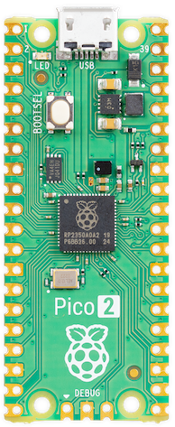
The Raspberry Pi Pico is a compact, low-cost microcontroller board built around the RP2040 chip. It features dual ARM Cortex-M0+ cores, 264KB of SRAM, and 2MB of onboard flash memory. Designed for versatility, the Pico supports programming in C, C++, MicroPython, and CircuitPython, making it an excellent choice for embedded systems, IoT applications, and rapid prototyping.
Explore Projects Built with Raspberry Pi Pico
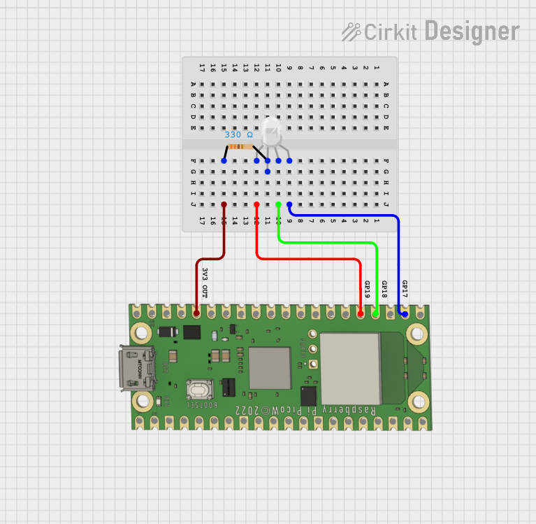
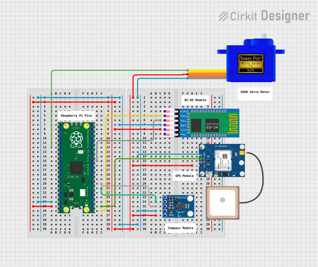

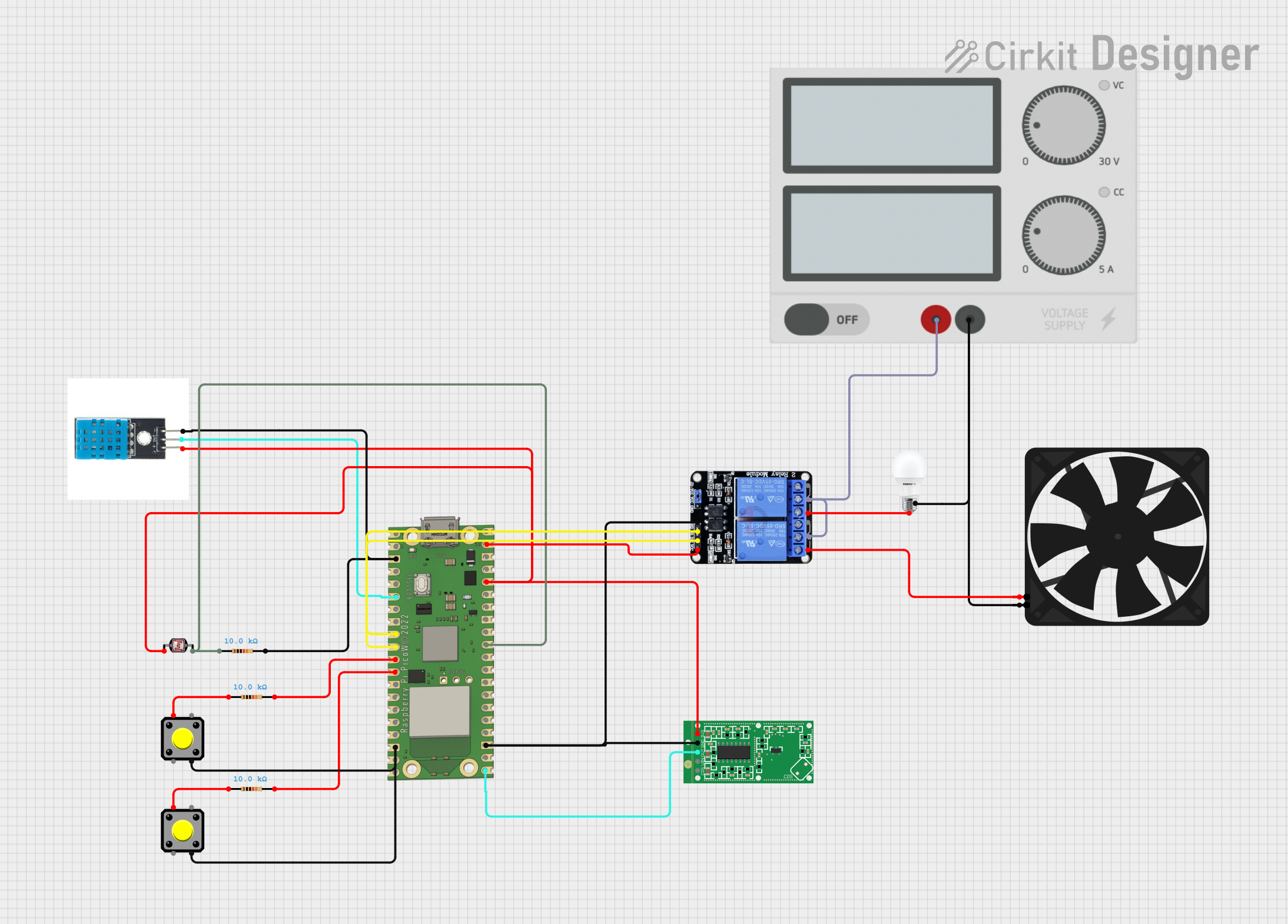
Explore Projects Built with Raspberry Pi Pico
Common Applications and Use Cases
- IoT devices and smart home automation
- Robotics and motor control
- Sensor interfacing and data logging
- Educational projects and learning microcontroller programming
- Prototyping for embedded systems
Technical Specifications
Key Technical Details
- Microcontroller: RP2040 (dual ARM Cortex-M0+ cores, up to 133MHz)
- Memory: 264KB SRAM, 2MB onboard QSPI flash
- GPIO Pins: 26 multi-function pins (3.3V logic level)
- Interfaces: I2C, SPI, UART, PWM, ADC (3 channels), USB 1.1
- Power Supply: 1.8V to 5.5V (via micro-USB or VSYS pin)
- Operating Temperature: -20°C to +85°C
- Dimensions: 51mm x 21mm
Pin Configuration and Descriptions
The Raspberry Pi Pico has 40 pins, including power, ground, and GPIO pins. Below is a summary of the pin configuration:
| Pin Number | Pin Name | Description |
|---|---|---|
| 1 | GP0 | GPIO0, UART0 TX, I2C0 SDA, SPI0 RX |
| 2 | GP1 | GPIO1, UART0 RX, I2C0 SCL, SPI0 CSn |
| 3 | GND | Ground |
| 4 | GP2 | GPIO2, UART1 TX, I2C1 SDA, SPI0 SCK |
| 5 | GP3 | GPIO3, UART1 RX, I2C1 SCL, SPI0 TX |
| 36 | 3V3 | 3.3V Power Output |
| 39 | VSYS | Power input (1.8V to 5.5V) |
| 40 | GND | Ground |
For a complete pinout diagram, refer to the official Raspberry Pi Pico documentation.
Usage Instructions
How to Use the Raspberry Pi Pico in a Circuit
- Powering the Pico:
- Use a micro-USB cable to power the Pico via the USB port.
- Alternatively, supply 1.8V to 5.5V to the VSYS pin for external power sources.
- Connecting GPIO Pins:
- GPIO pins operate at 3.3V logic levels. Use level shifters if interfacing with 5V devices.
- Configure pins as input, output, or alternate functions (e.g., I2C, SPI) in your code.
- Programming the Pico:
- Connect the Pico to your computer via USB.
- Hold the BOOTSEL button while plugging in the USB cable to enter USB mass storage mode.
- Drag and drop the firmware file (e.g., MicroPython UF2) onto the Pico's storage.
Important Considerations and Best Practices
- Avoid exceeding the 3.3V logic level on GPIO pins to prevent damage.
- Use decoupling capacitors when connecting sensors or modules to reduce noise.
- For power-hungry peripherals, ensure the power supply can handle the additional current.
Example: Blinking an LED with MicroPython
Below is an example of how to blink an LED connected to GPIO25 using MicroPython:
Import the machine module to control hardware and the time module for delays
import machine import time
Configure GPIO25 (onboard LED) as an output pin
led = machine.Pin(25, machine.Pin.OUT)
Blink the LED in an infinite loop
while True: led.value(1) # Turn the LED on time.sleep(1) # Wait for 1 second led.value(0) # Turn the LED off time.sleep(1) # Wait for 1 second
Example: Reading an Analog Sensor
The following example demonstrates how to read an analog sensor connected to GPIO26 (ADC0):
Import the machine module to access ADC and the time module for delays
import machine import time
Configure GPIO26 as an ADC input
adc = machine.ADC(26)
Read and print the ADC value in an infinite loop
while True: value = adc.read_u16() # Read 16-bit ADC value (0-65535) print("ADC Value:", value) # Print the value to the console time.sleep(0.5) # Wait for 0.5 seconds
Troubleshooting and FAQs
Common Issues and Solutions
Pico Not Detected by Computer:
- Ensure the BOOTSEL button is held down while connecting the Pico to the computer.
- Check the USB cable (some cables are power-only and do not support data transfer).
- Verify that the Pico is receiving power (check the onboard LED).
GPIO Pin Not Responding:
- Confirm the pin is correctly configured in your code (input, output, or alternate function).
- Check for loose connections or incorrect wiring.
- Ensure the voltage levels are within the 3.3V range.
Program Not Running After Power Cycle:
- Ensure the program is saved to the Pico's flash memory.
- If using MicroPython, ensure the script is named
main.pyto run automatically on boot.
FAQs
Can I use the Pico with Arduino IDE?
Yes, the Raspberry Pi Pico is compatible with the Arduino IDE. Install the RP2040 board package to get started.What is the maximum current output of the 3.3V pin?
The 3.3V pin can supply up to 300mA, depending on the input power source.Can I use the Pico for battery-powered projects?
Yes, the Pico can be powered via the VSYS pin using a battery (e.g., LiPo or AA batteries). Ensure the voltage is within the 1.8V to 5.5V range.How do I reset the Pico to factory settings?
Reflash the original firmware by entering USB mass storage mode and copying the appropriate UF2 file to the Pico.
By following this documentation, you can effectively use the Raspberry Pi Pico for a wide range of projects and applications.