Cirkit Designer Logo
Cirkit Designer
Your all-in-one circuit design IDE
Home / 
Component Documentation

How to Use RFM210LCF: Examples, Pinouts, and Specs

Image of RFM210LCF
Cirkit Designer LogoDesign with RFM210LCF in Cirkit Designer

Introduction

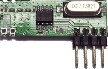
The RFM210LCF is a low-power, long-range RF transceiver module manufactured by Hope Microelectronics. Designed for wireless communication, it operates in the 433 MHz frequency band and is ideal for applications requiring reliable and efficient data transmission. Its compact design and ease of integration make it a popular choice for developers working on remote control systems, telemetry, and sensor networks.

Explore Projects Built with RFM210LCF

Use Cirkit Designer to design, explore, and prototype these projects online. Some projects support real-time simulation. Click "Open Project" to start designing instantly!
Dual-Mode LoRa and GSM Communication Device with ESP32
Image of modul gateway: A project utilizing RFM210LCF in a practical application
This circuit features an ESP32 Devkit V1 microcontroller interfaced with an RFM95 LoRa transceiver module for long-range communication and a SIM800L GSM module for cellular connectivity. Two LM2596 step-down modules are used to regulate the 12V battery voltage down to 3.3V required by the ESP32, RFM95, and SIM800L. The ESP32 facilitates data exchange between the RFM95 and SIM800L, enabling the system to send/receive data over both LoRa and GSM networks.
Cirkit Designer LogoOpen Project in Cirkit Designer
ESP8266-Controlled Wireless EV Charging System with RFID Authentication
Image of Minor Project: A project utilizing RFM210LCF in a practical application
This circuit appears to be a wireless charging system with RFID access control, powered by an AC supply that is rectified and regulated. It includes an ESP8266 microcontroller for managing the charging process and displaying status information on an OLED display. The RFID-RC522 module is used to authorize the charging process, and a MOSFET is likely used to control the power to the charging coil.
Cirkit Designer LogoOpen Project in Cirkit Designer
Biometric and RFID Security System with Dual Adafruit Feather nRF52840 Controllers
Image of Rfid access control: A project utilizing RFM210LCF in a practical application
This circuit features two Adafruit Feather nRF52840 microcontrollers, each interfaced with an RFID-RC522 module for RFID communication and an AT24C256 external EEPROM for additional memory storage. One of the microcontrollers is also connected to an R307 Fingerprint Sensor for biometric input, and both microcontrollers are powered by a shared power supply and a coin cell breakout for backup or RTC power. The circuit is likely designed for secure access control or identification purposes, utilizing both RFID and fingerprint authentication, with data storage capabilities.
Cirkit Designer LogoOpen Project in Cirkit Designer
Arduino Nano-Based GPS Tracker with GSM and LoRa Communication
Image of Electromagnetic Sensor: A project utilizing RFM210LCF in a practical application
This circuit features an Arduino Nano microcontroller interfaced with an RFM95 LoRa transceiver module for long-range communication, a SIM800L GSM module for cellular connectivity, and a GPS NEO 6M module for location tracking. The Arduino Nano also connects to an inductive sensor for proximity or metal detection. The circuit is designed for applications requiring wireless communication, location tracking, and proximity sensing, with the Arduino Nano serving as the central processing unit.
Cirkit Designer LogoOpen Project in Cirkit Designer

Explore Projects Built with RFM210LCF

Use Cirkit Designer to design, explore, and prototype these projects online. Some projects support real-time simulation. Click "Open Project" to start designing instantly!
Image of modul gateway: A project utilizing RFM210LCF in a practical application
Dual-Mode LoRa and GSM Communication Device with ESP32
This circuit features an ESP32 Devkit V1 microcontroller interfaced with an RFM95 LoRa transceiver module for long-range communication and a SIM800L GSM module for cellular connectivity. Two LM2596 step-down modules are used to regulate the 12V battery voltage down to 3.3V required by the ESP32, RFM95, and SIM800L. The ESP32 facilitates data exchange between the RFM95 and SIM800L, enabling the system to send/receive data over both LoRa and GSM networks.
Cirkit Designer LogoOpen Project in Cirkit Designer
Image of Minor Project: A project utilizing RFM210LCF in a practical application
ESP8266-Controlled Wireless EV Charging System with RFID Authentication
This circuit appears to be a wireless charging system with RFID access control, powered by an AC supply that is rectified and regulated. It includes an ESP8266 microcontroller for managing the charging process and displaying status information on an OLED display. The RFID-RC522 module is used to authorize the charging process, and a MOSFET is likely used to control the power to the charging coil.
Cirkit Designer LogoOpen Project in Cirkit Designer
Image of Rfid access control: A project utilizing RFM210LCF in a practical application
Biometric and RFID Security System with Dual Adafruit Feather nRF52840 Controllers
This circuit features two Adafruit Feather nRF52840 microcontrollers, each interfaced with an RFID-RC522 module for RFID communication and an AT24C256 external EEPROM for additional memory storage. One of the microcontrollers is also connected to an R307 Fingerprint Sensor for biometric input, and both microcontrollers are powered by a shared power supply and a coin cell breakout for backup or RTC power. The circuit is likely designed for secure access control or identification purposes, utilizing both RFID and fingerprint authentication, with data storage capabilities.
Cirkit Designer LogoOpen Project in Cirkit Designer
Image of Electromagnetic Sensor: A project utilizing RFM210LCF in a practical application
Arduino Nano-Based GPS Tracker with GSM and LoRa Communication
This circuit features an Arduino Nano microcontroller interfaced with an RFM95 LoRa transceiver module for long-range communication, a SIM800L GSM module for cellular connectivity, and a GPS NEO 6M module for location tracking. The Arduino Nano also connects to an inductive sensor for proximity or metal detection. The circuit is designed for applications requiring wireless communication, location tracking, and proximity sensing, with the Arduino Nano serving as the central processing unit.
Cirkit Designer LogoOpen Project in Cirkit Designer

Common Applications

  • Remote control systems (e.g., garage doors, home automation)
  • Wireless sensor networks
  • Telemetry and data acquisition
  • Industrial monitoring and control
  • Internet of Things (IoT) devices

Technical Specifications

The following table outlines the key technical details of the RFM210LCF module:

Parameter Value
Operating Frequency 433 MHz
Modulation Type FSK (Frequency Shift Keying)
Supply Voltage 1.8V to 3.6V
Current Consumption 9.5 mA (transmit mode, typical)
Sensitivity -110 dBm (at 2.4 kbps)
Output Power Up to +10 dBm
Data Rate 1.2 kbps to 256 kbps
Operating Temperature -40°C to +85°C
Dimensions 16 mm x 16 mm x 2 mm

Pin Configuration and Descriptions

The RFM210LCF module has a simple pinout for easy integration. Below is the pin configuration:

Pin Number Pin Name Description
1 VCC Power supply input (1.8V to 3.6V)
2 GND Ground connection
3 ANT Antenna connection for RF signal
4 SDI Serial Data Input (SPI interface)
5 SDO Serial Data Output (SPI interface)
6 SCK Serial Clock Input (SPI interface)
7 CS Chip Select (active low)
8 IRQ Interrupt Request Output (indicates events)

Usage Instructions

How to Use the RFM210LCF in a Circuit

  1. Power Supply: Connect the VCC pin to a regulated power source (1.8V to 3.6V) and the GND pin to the ground of your circuit.
  2. Antenna: Attach a 50-ohm antenna to the ANT pin for optimal RF performance.
  3. SPI Communication: Use the SDI, SDO, SCK, and CS pins to interface with a microcontroller via the SPI protocol.
  4. Interrupt Handling: Connect the IRQ pin to a GPIO pin on your microcontroller to handle events such as data reception or transmission completion.

Important Considerations

  • Antenna Design: Ensure the antenna is properly matched to the 433 MHz frequency band for maximum range and efficiency.
  • Power Supply Decoupling: Use a decoupling capacitor (e.g., 0.1 µF) close to the VCC pin to reduce noise and improve stability.
  • SPI Configuration: Configure the SPI interface on your microcontroller to match the RFM210LCF's requirements (e.g., clock polarity and phase).
  • Regulatory Compliance: Ensure your application complies with local RF regulations for the 433 MHz band.

Example: Connecting to an Arduino UNO

Below is an example of how to connect the RFM210LCF to an Arduino UNO and send data:

Wiring Diagram

RFM210LCF Pin Arduino UNO Pin
VCC 3.3V
GND GND
SDI D11 (MOSI)
SDO D12 (MISO)
SCK D13 (SCK)
CS D10
IRQ D2

Arduino Code Example

#include <SPI.h>

// Define RFM210LCF pins
#define CS_PIN 10
#define IRQ_PIN 2

void setup() {
  // Initialize serial communication for debugging
  Serial.begin(9600);

  // Initialize SPI
  SPI.begin();
  pinMode(CS_PIN, OUTPUT);
  digitalWrite(CS_PIN, HIGH); // Set CS high to deselect the module

  // Configure IRQ pin
  pinMode(IRQ_PIN, INPUT);

  Serial.println("RFM210LCF Initialized");
}

void loop() {
  // Example: Send a command to the RFM210LCF
  digitalWrite(CS_PIN, LOW); // Select the module
  SPI.transfer(0x01);        // Send a dummy command (replace with actual command)
  digitalWrite(CS_PIN, HIGH); // Deselect the module

  // Check for IRQ events
  if (digitalRead(IRQ_PIN) == LOW) {
    Serial.println("IRQ Event Detected");
    // Handle the event (e.g., read received data)
  }

  delay(1000); // Wait 1 second
}

Troubleshooting and FAQs

Common Issues and Solutions

  1. No RF Signal Detected

    • Solution: Verify the antenna connection and ensure it is tuned for the 433 MHz band.
    • Solution: Check the power supply voltage and ensure it is within the specified range (1.8V to 3.6V).
  2. SPI Communication Fails

    • Solution: Ensure the SPI pins are correctly connected and configured on the microcontroller.
    • Solution: Verify the SPI clock settings (e.g., polarity and phase) match the RFM210LCF's requirements.
  3. Short Range or Poor Signal Quality

    • Solution: Use a high-quality 50-ohm antenna and minimize obstructions between the transmitter and receiver.
    • Solution: Add a decoupling capacitor near the VCC pin to reduce noise.
  4. IRQ Pin Not Triggering

    • Solution: Ensure the IRQ pin is connected to a GPIO pin configured as an input.
    • Solution: Check the RFM210LCF's configuration to ensure interrupts are enabled.

FAQs

Q: Can the RFM210LCF operate at frequencies other than 433 MHz?
A: No, the RFM210LCF is specifically designed for the 433 MHz frequency band.

Q: What is the maximum data rate supported by the RFM210LCF?
A: The module supports data rates up to 256 kbps.

Q: Is the RFM210LCF suitable for battery-powered applications?
A: Yes, its low power consumption makes it ideal for battery-powered devices.

Q: Does the RFM210LCF support encryption?
A: No, the module does not have built-in encryption. You can implement encryption at the software level on your microcontroller.